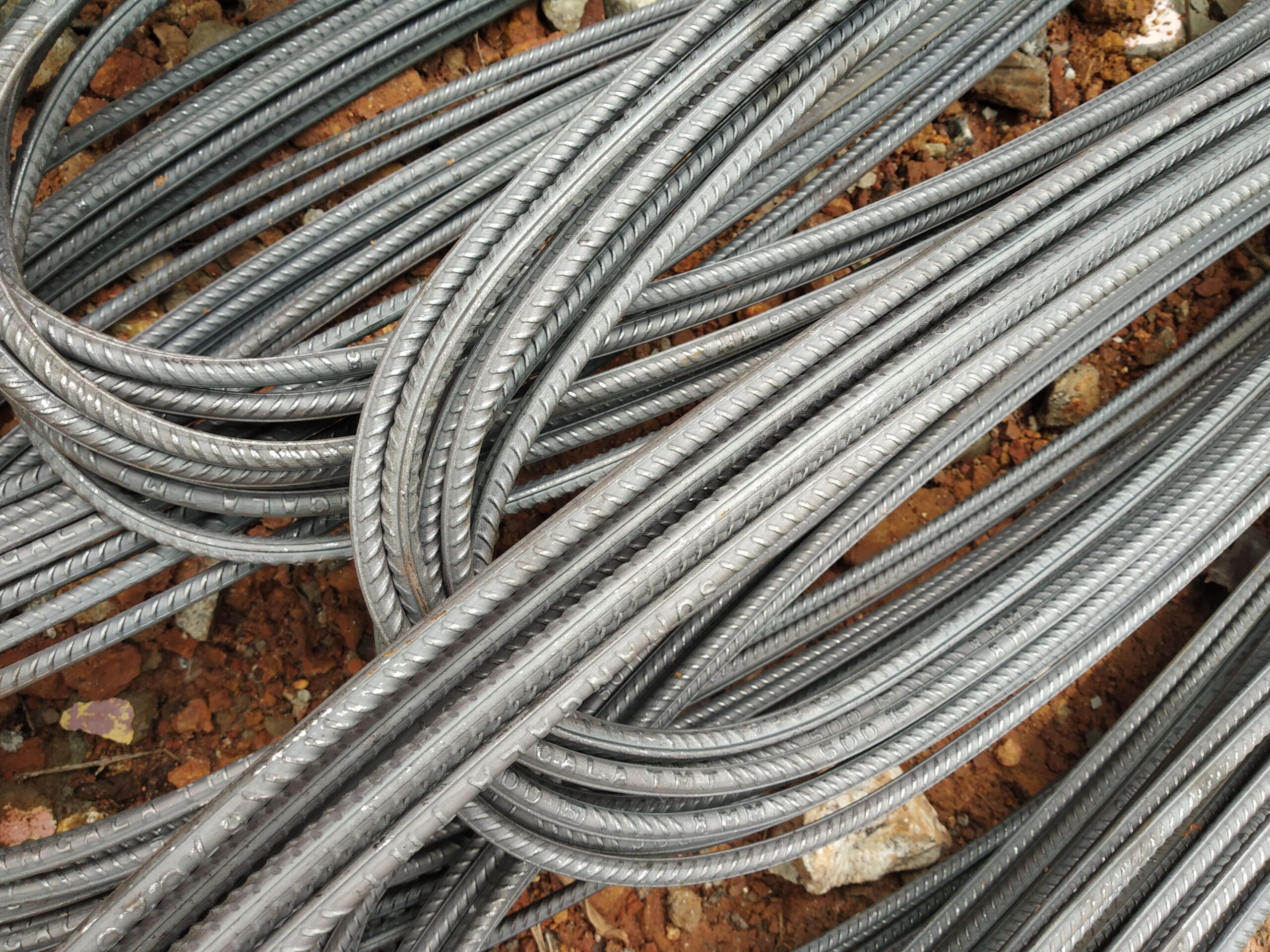
Rebar for Water Tanks: Sizes, Detailing & Quantities
Reinforced concrete water tanks must resist hydrostatic pressure, prevent cracking that could cause leakage, and withstand aggressive moisture exposure throughout their service life. This guide covers typical bar sizes, spacing, concrete cover and quantity estimation for RC water tank construction — general guidance aligned with DIN 488 and Eurocode 2 principles.
Structural Demands on Water Tank Reinforcement
Reinforced concrete water tanks — whether underground service reservoirs, elevated storage tanks or above-ground municipal tanks — impose unique demands on the reinforcement cage. Unlike typical structural slabs or beams, water-retaining structures must satisfy two simultaneous design objectives: structural strength and crack width limitation to prevent leakage.
Crack width limits under Eurocode 2 (EN 1992-1-1) and the specialist water-retaining structure standard EN 1992-3 are stringent: for critical water-retaining structures, the design crack width wk is limited to 0.05–0.1 mm. This drives higher reinforcement ratios and closer bar spacings than purely structural design would require. B500B rebar (DIN 488, EN 10080) is the standard grade — 500 MPa yield, high ductility, ribbed surface for excellent bond.
Typical Bar Sizes for RC Water Tanks
Wall and base slab reinforcement must be provided in two directions (horizontal and vertical in walls; both orthogonal directions in base slabs). The table below gives indicative sizes for commonly encountered tank geometries:
| Element | Bar Dia (mm) | Spacing (mm) | Weight kg/m | Section mm²/m |
|---|---|---|---|---|
| Wall vertical bars (inner face) | 12–16 | 100–150 | 0.888–1.58 | 754–1340 |
| Wall horizontal bars (outer face) | 10–12 | 150–200 | 0.617–0.888 | 393–503 |
| Base slab bottom mesh (both ways) | 12–16 | 150–200 | 0.888–1.58 | 503–838 |
| Base slab top mesh (both ways) | 10–12 | 150–200 | 0.617–0.888 | 393–503 |
| Roof slab (if covered) | 10–12 | 150–200 | 0.617–0.888 | 393–503 |
Wall thickness for rectangular RC tanks typically ranges from 200 mm for shallow tanks up to 400 mm or more for deep tanks, with total reinforcement ratios of 0.4–0.8 % of the gross section area per face per direction.
Concrete Cover for Water-Retaining Structures
Concrete cover in water tanks must address both structural durability and the water-retaining function. Typical values per EN 1992-1-1 and EN 1992-3:
- Inner face (water side): minimum nominal cover cnom = 40 mm, exposure class XC4/XD2 or more severe in potable water contexts.
- Outer face (soil or atmosphere): 35–50 mm depending on exposure; buried sections often require 50 mm with XC2/XC3 classification.
- Base slab underside: 50–75 mm where cast directly onto blinding; 40 mm with adequate blinding quality.
Correct cover is achieved using proprietary plastic rebar spacers and chairs at maximum 800 mm centres in both directions. The right spacer type prevents bar displacement during concrete pour and vibration.
Crack Control: The Governing Design Criterion
In water-retaining structures, crack control frequently governs the reinforcement design rather than ultimate limit state strength. The approach under EN 1992-3 divides structures into tightness classes (0–3); municipal water storage typically requires Tightness Class 1 or 2, limiting calculated crack width to 0.1 mm or less at the liquid face.
To achieve these crack widths, designers typically:
- Use smaller diameter bars at closer centres rather than large bars at wide spacing — smaller bars provide greater surface area for bond and finer crack distribution.
- Detail construction joints with water-bars and ensure that reinforcement is continuous (or properly lapped) across the joint.
- Use high-performance concrete (typically C30/37 or C35/45 with low w/c ratio and possible admixtures for water-tightness).
- Consider early thermal cracking from cement hydration heat in thick walls; T12 or T16 bars at 150 mm are common in thick walls to control early-age cracking.
Full documentation including EN 10204 3.1 Mill Test Certificates supports independent verification of rebar yield and elongation properties, which are inputs to crack width calculations.
Quantity Estimation for Water Tank Rebar
A simplified approach for estimating reinforcement quantity in a rectangular RC water tank:
- Calculate wall area per face: (2L + 2W) × H per face, both inner and outer reinforcement layers.
- Calculate base slab area: L × W, top and bottom mats in both directions.
- Apply bar spacing to determine bar count per layer; multiply by bar length plus laps (typically 40–50 × d).
- Use the weight formula: kg/m = d²(mm) × 0.00617. For T12: 0.888 kg/m; T16: 1.58 kg/m.
- Add 8–12 % for laps, wall corners, starter bars and wastage.
A typical 5 m × 5 m × 3 m deep RC tank with 250 mm walls and T12 @ 150 mm both-ways both-faces might consume 4,000–6,000 kg of reinforcement, depending on the roof slab and detailing complexity.
Related Resources
For complete reinforcement procurement, explore our Applications hub and related articles on Rebar for Raft Foundations and Rebar for Swimming Pools. All supply includes EN 10204 3.1 Mill Test Certificate, Certificate of Origin and CE Declaration of Performance.
Frequently Asked Questions
Common questions about reinforcement sizing and detailing for RC water tanks.
What bar size is typically used for RC water tank walls?
Why is crack control more important than strength in water tanks?
What concrete cover is needed on the water-retaining face?
What rebar grade is correct for water-retaining structures?
Do I need Mill Test Certificates for water tank rebar supply?
Source German-standard rebar with full export documentation
Tell us your specification and destination port — we’ll respond with a detailed quotation.