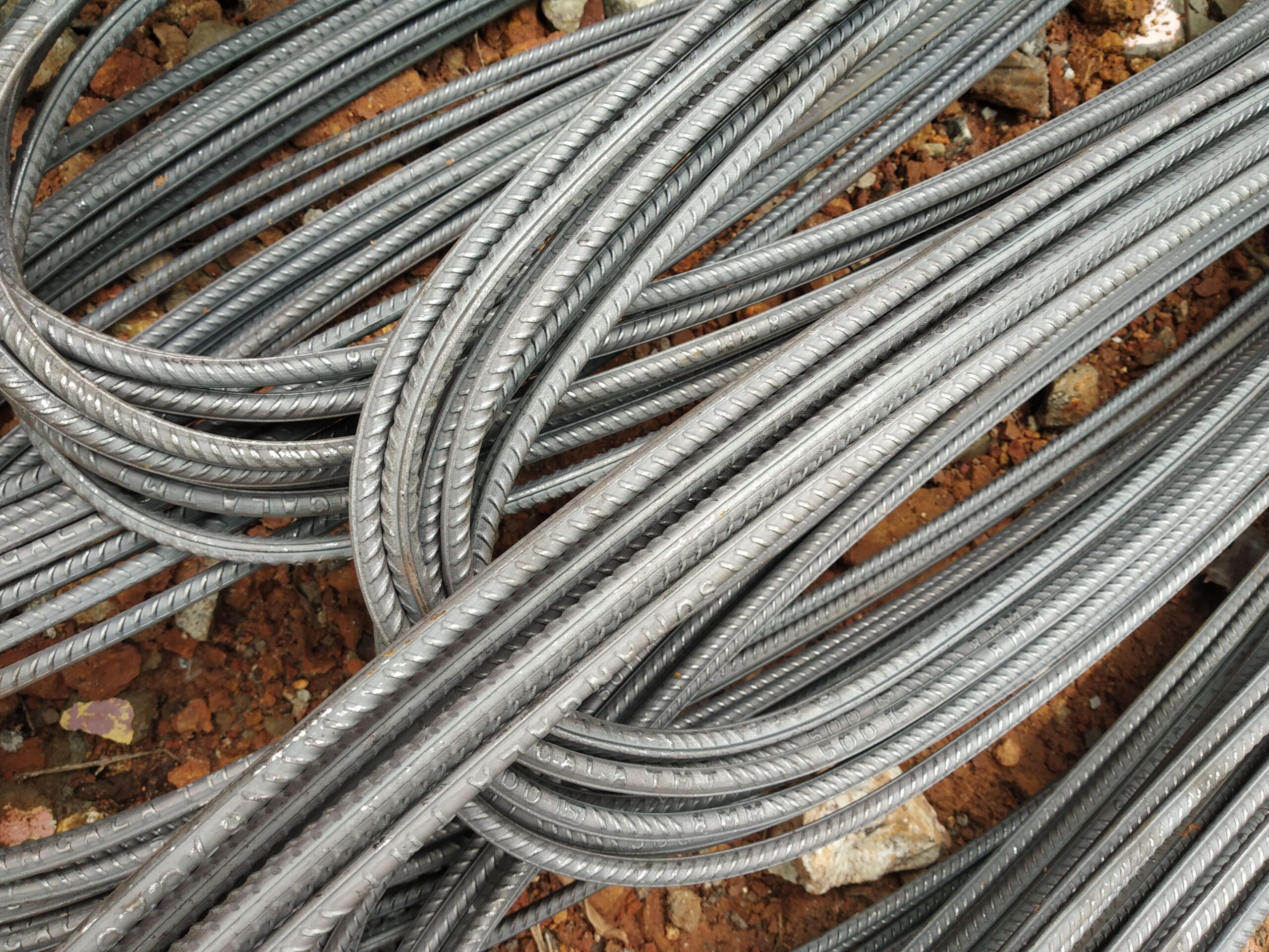
How Much Should Rebar Overlap (Lap Length)?
Lap length — the overlap required where two rebar bars join end-to-end — is one of the most critical details in reinforced concrete. Too short and the splice fails; too long and you waste material. Eurocode 2 sets out the rules precisely.
What Is a Lap Splice and Why Is It Needed?
Reinforcing bars are manufactured and supplied in finite lengths — typically 6 m, 12 m, or up to 18 m for B500B straight bars to DIN 488. Real structures are often taller, longer, or deeper than a single bar length. Where one bar ends, another must begin, and the two must transfer tensile force across the joint as reliably as if the steel were continuous.
A lap splice achieves this by overlapping two bars side-by-side for a calculated length, relying on bond between the ribbed bar surface and the surrounding concrete to transfer force from one bar to the other through the concrete matrix. The overlap length required is called the lap length (or sometimes lap splice length), designated l0 in Eurocode 2.
The Eurocode 2 Approach to Lap Length
Eurocode 2 clause 8.7 governs lap splices. The lap length l0 is derived from the anchorage length lbd, multiplied by a factor α6 that accounts for the percentage of bars lapped at a single cross-section:
- l0 = α1 × α2 × α3 × α5 × α6 × lb,rqd
- The basic required anchorage length lb,rqd = (φ/4) × (σsd/fbd), where φ is bar diameter, σsd is design stress in the bar, and fbd is the design bond stress.
- fbd = 2.25 × η1 × η2 × fctd, where η1 accounts for bond quality (1.0 for good bond; 0.7 for poor bond), η2 for bar size, and fctd is the design tensile strength of concrete.
- α6 = 1.4 when more than 50% of bars are lapped at one section; 1.0 when ≤ 25% are lapped.
The minimum lap length l0,min is the greater of 0.3 × α6 × lb,rqd, 15φ, or 200 mm.
The “40d Rule of Thumb” — and Its Important Caveats
A frequently quoted simplification is that rebar laps should be approximately 40 bar diameters (40d). For a Ø16 mm bar, 40d = 640 mm; for Ø20 mm, 40d = 800 mm. This rule of thumb has a basis in Eurocode 2 calculations for typical conditions — C25/30 concrete, B500B steel at full design stress, good bond conditions, ≤ 25% of bars lapped — but it is not universally correct:
- Shorter laps may be acceptable if the bar is not at full design stress at the lap location (e.g. near a point of contraflexure).
- Longer laps are required for larger bar diameters (η2 factor reduces fbd for φ > 32 mm), weaker concrete, poor bond conditions (bars in the top of a deep pour), or high percentages of lapped bars.
- Seismic critical regions under Eurocode 8 require a minimum lap length multiplied by a factor that accounts for ductility class — laps in critical regions may not be permitted at all in certain seismic design situations.
- B500C grade (seismic, Agt ≥ 7.5%, 1.15 ≤ k < 1.35) demands careful lap design as the higher strain capacity must be maintained through the splice.
Indicative Lap Lengths for B500B Bars in C25/30 Concrete
| Bar Dia (mm) | Weight (kg/m) | Indicative Lap (≤25% lapped) | Indicative Lap (>50% lapped) |
|---|---|---|---|
| Ø10 | 0.617 | ~380 mm (≈38d) | ~530 mm (≈53d) |
| Ø12 | 0.888 | ~450 mm (≈38d) | ~630 mm (≈53d) |
| Ø16 | 1.58 | ~600 mm (≈38d) | ~840 mm (≈53d) |
| Ø20 | 2.47 | ~760 mm (≈38d) | ~1060 mm (≈53d) |
| Ø25 | 3.85 | ~950 mm (≈38d) | ~1330 mm (≈53d) |
| Ø32 | 6.31 | ~1220 mm (≈38d) | ~1700 mm (≈53d) |
These indicative figures assume C25/30 concrete, good bond conditions, full design stress, and α1–α5 = 1.0. They are for guidance only — always verify with your structural engineer.
Mechanical Couplers as an Alternative to Lap Splices
For large-diameter bars (Ø25–Ø40 mm), long lap splices become impractical and congested. Mechanical rebar couplers — parallel-thread or taper-thread — provide a compact, reliable alternative that transfers the full tensile (and sometimes compressive) capacity of the bar without the concrete congestion that accompanies long laps. Coupler lengths are typically only 2–3 times the bar diameter, compared to 38–53d for a lap.
Steel Rebar Germany supplies mechanical splicing couplers for B500B bars in diameters 12–40 mm, alongside B500A, B500B, and B500C bar in standard lengths for projects worldwide.
Staggering of Laps
Eurocode 2 cl. 8.7.2 requires that laps in adjacent bars be staggered — not placed at the same cross-section simultaneously — unless the design accounts for the α6 factor for closely grouped laps. The recommended minimum distance between adjacent lap centres is 0.3 × l0 in the longitudinal direction, and the clear transverse distance between lapped bars must not exceed 4φ or 50 mm, otherwise the lap must be designed as individual (not adjacent) splices.
Frequently Asked Questions
Key questions about rebar lap length, Eurocode 2 requirements, and mechanical splicing alternatives.
What is the standard rebar lap length in Eurocode 2?
Does the “40d rule” always apply for rebar overlaps?
Can laps be placed anywhere along a bar?
What is the difference between lap length and anchorage length?
When should I use mechanical couplers instead of lap splices?
Source German-standard rebar with full export documentation
Tell us your specification and destination port — we’ll respond with a detailed quotation.