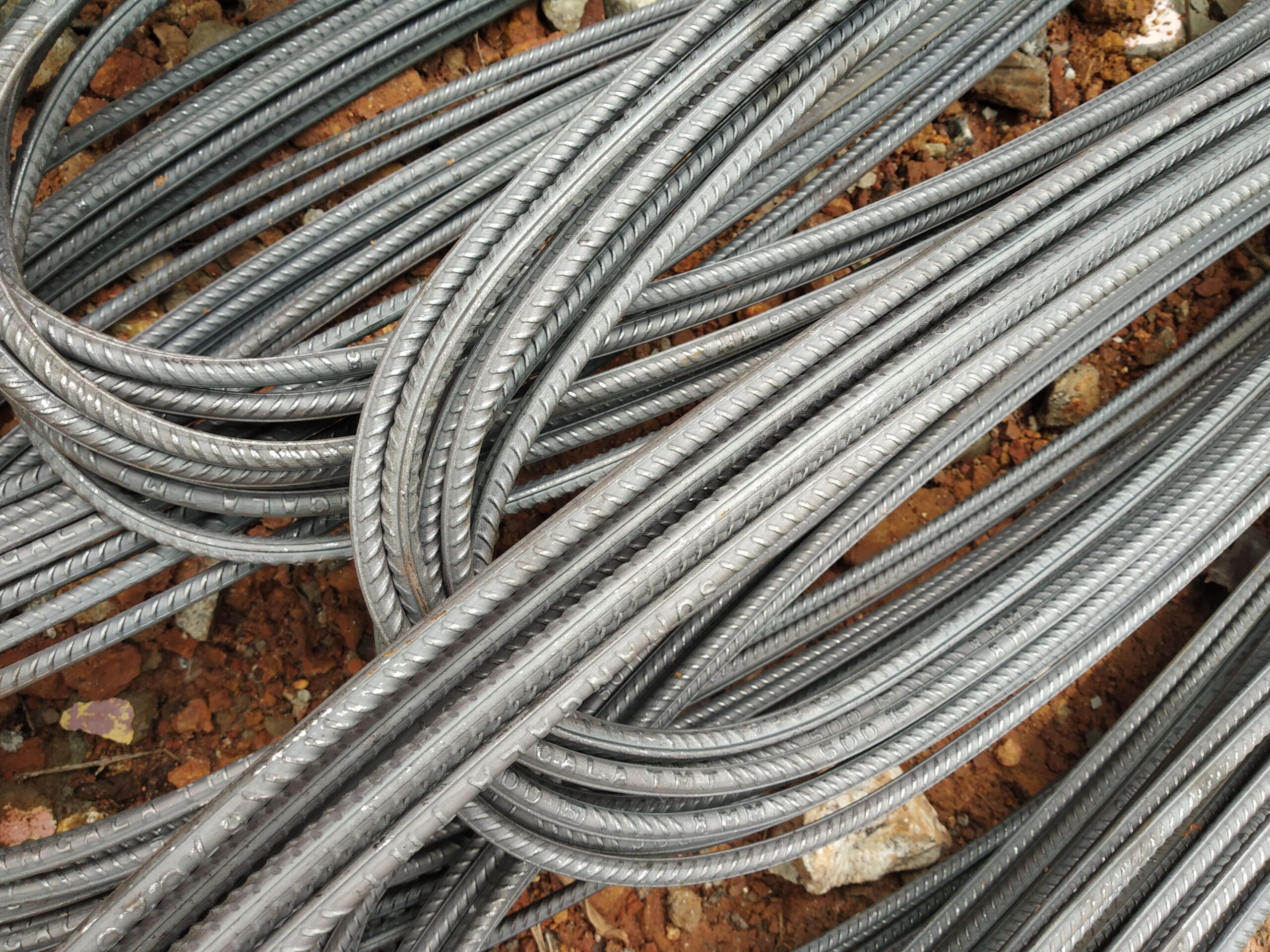
Reinforcing Steel for Diaphragm Walls — DIN 488 / EN 10080 Supply
Diaphragm walls demand large-format reinforcement cages assembled to precise tolerances and lowered into bentonite-supported trenches before concreting. Steel Rebar Germany supplies B500B bar and cut-and-bend elements to DIN 488 / EN 10080 for diaphragm wall projects worldwide.
What is a Diaphragm Wall and How is it Reinforced?
A diaphragm wall (German: Schlitzwand) is a continuous in-situ reinforced concrete retaining wall constructed by excavating individual panels in a bentonite-stabilised trench, assembling a prefabricated reinforcement cage, and casting concrete by tremie pipe — displacing the bentonite slurry as the concrete rises. Diaphragm walls are used for deep basement construction, cut-and-cover tunnels, flood defence, and as permanent retaining structures in urban environments where space for battered excavation slopes is unavailable.
The reinforcement cage for each panel is typically assembled above ground and lowered as a unit or in sections into the trench. Panel widths are commonly 600–1000 mm; depths range from 10 m in shallow urban basements to 60 m or more in deep shaft and tunnel applications. The reinforcement must be rigid enough to maintain its geometry during lowering through the bentonite slurry and to resist the horizontal earth and water pressures it will carry once the basement is excavated.
Typical Bar Sizes and Cage Arrangement
Indicative values below reflect common practice in diaphragm wall design. Actual bar sizes and spacings are determined by the geotechnical design to EC7, the structural design to Eurocode 2, and the project-specific panel geometry.
| Reinforcement element | Typical dia. (mm) | Weight kg/m | Section mm² | Function |
|---|---|---|---|---|
| Vertical main bars (front and back face) | 16–32 | 1.58–6.31 | 201–804 | Bending and tension under earth/water pressure |
| Horizontal distribution bars | 12–20 | 0.888–2.47 | 113–314 | Crack control, shear distribution across panel width |
| Cage stiffeners / lattice bars | 16–25 | 1.58–3.85 | 201–491 | Cage rigidity during lowering, link to panel edges |
| Splice / continuity starter bars | 16–32 | 1.58–6.31 | 201–804 | Connection to basement slab and floor structures |
Cover in Diaphragm Walls — the Challenge of Tremie Concreting
Achieving consistent concrete cover in a diaphragm wall cage is more difficult than in a conventional formed element because the concrete is placed by tremie pipe and the cage faces an excavated soil or bentonite face rather than formwork. Cover is typically achieved through:
- Cover spacers on the cage faces: Proprietary roller or block spacers clipped to the horizontal bars maintain the design cover (commonly 75–100 mm nominal in aggressive subsoil environments) as the cage is lowered past the panel edges.
- Panel edge guides: Structural steel guide sections welded to the cage ends ensure the cage maintains lateral position within the excavated panel during lowering.
- Bar diameters and lap design: Large-diameter bars (20–32 mm) are standard for diaphragm wall verticals because they provide a wider tolerance margin relative to their own diameter and resist the physical forces of cage lowering better than smaller bars at equivalent area.
Starter Bars and Connection to Basement Structure
Where the diaphragm wall is to act as the permanent basement wall, starter bars must be cast into the panel to connect the floor slabs and basement base slab to the wall. This typically involves horizontal U-bars or looped starters at each floor level position, often with mechanical couplers (rebar couplers) to simplify the connection of the floor slab reinforcement to the wall face. Planning the starter bar arrangement before cage fabrication is essential — they are extremely difficult to add after concreting.
Cut-and-Bend Supply for Diaphragm Wall Cages
Our cut-and-bend service produces all elements required for diaphragm wall cages: straight main bars to length, horizontal distribution bars, closed U-frames, panel guide sections, and shaped starters. Elements are bundled and labelled by cage section for direct assembly. See also: Reinforcing Steel for Foundations & Piling for related deep works supply.
Export and Documentation
Mill Test Certificates to EN 10204 3.1, Certificate of Origin, CE marking / Declaration of Performance, and seaworthy packing accompany all diaphragm wall reinforcement orders. Materials are available for container or break-bulk shipment to project sites internationally.
Frequently Asked Questions — Diaphragm Wall Reinforcement
What rebar grade is used for diaphragm wall cages?
How is concrete cover maintained in a diaphragm wall cage?
What bar diameters are typical for diaphragm wall vertical reinforcement?
Can you supply starter bars and couplers for diaphragm wall connections?
What documentation do you provide for diaphragm wall reinforcement orders?
Source German-standard rebar with full export documentation
Tell us your diaphragm wall reinforcement specification and destination port — we’ll respond with a detailed quotation.