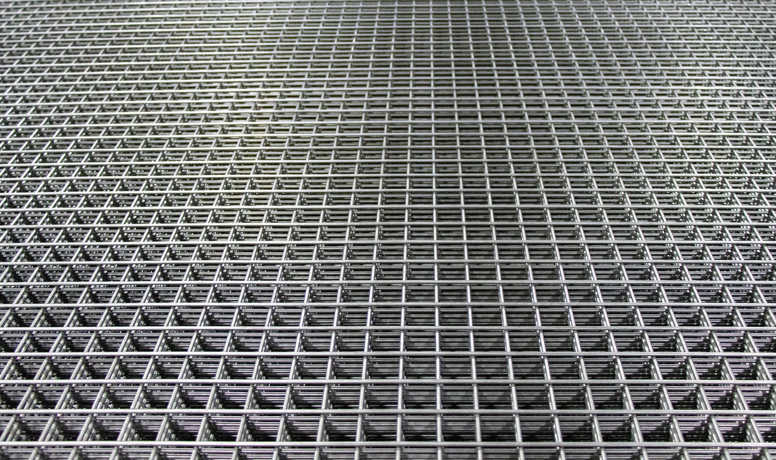
Cutting Welded Mesh on Site: Methods, Waste, and Specification Compliance
Cutting welded reinforcing mesh on site is a routine but technically important operation. This guide covers the correct tools and techniques for cutting DIN 488-4 and EN 10080 mesh panels, how to minimise material waste through intelligent sheet layout, and what the standards say about maintaining reinforcement integrity at cut edges.
Why Mesh Cutting Requires More Care Than Straight Bar Cutting
Cutting welded reinforcing mesh is not simply cutting individual bars. A mesh panel is a structural grid: removing wires from the grid — particularly those that cross the main load-direction wires — changes the effective area of reinforcement provided at a section. Careless cutting can leave a pour with less steel than the design specifies, potentially violating minimum reinforcement requirements under EN 1992-1-1 (Eurocode 2) at the cut edge.
The key difference between cutting a single bar and cutting mesh is that mesh has two reinforcement directions. The main wires (typically longitudinal, carrying the primary design load) and the secondary or distribution wires (transverse, maintaining bar spacing and carrying shrinkage and temperature forces) must both be accounted for in the cut layout. Cutting too close to a weld intersection can also weaken the weld node, reducing the integrity of the grid.
German-standard reinforcing mesh supplied to DIN 488-4 uses B500A wire (cold-worked, normal ductility, k ≥ 1.05, Agt ≥ 2.5 %) in both directions. Standard panels are available in sizes up to 6.0 × 2.3 m in Q-type (square mesh) and R-type (rectangular mesh) configurations, with wire diameters from 4 mm to 12 mm and nominal wire spacings of 100–200 mm.
Standard Mesh Designations and Wire Dimensions
Understanding the mesh designation helps determine what area of steel is lost when a panel is trimmed. The table below shows common Q-type mesh panels used in slab and wall construction:
| Designation | Wire dia (mm) | Spacing (mm) | Area per m width (mm²/m) | Weight (kg/m²) |
|---|---|---|---|---|
| Q131 | 4.0 | 150 × 150 | 131 | 1.54 |
| Q188 | 4.9 | 100 × 100 (approx.) | 188 | 2.21 |
| Q257 | 5.7 | 100 × 100 | 257 | 3.02 |
| Q335 | 6.5 | 100 × 100 | 335 | 3.93 |
| Q424 | 7.3 | 100 × 100 | 424 | 4.97 |
| Q524 | 8.1 | 100 × 100 | 524 | 6.15 |
| Q636 | 9.0 | 100 × 100 | 636 | 7.45 |
When a panel is cut, the remaining piece must still deliver the design-specified area (mm²/m) across the full width at every section within the slab. If the cut removes a wire row, the effective area per metre drops. For example, cutting a Q335 panel along a line that removes one 6.5 mm wire from every 100 mm module reduces the local area to approximately 299 mm²/m — a 10 % shortfall that may or may not be acceptable depending on the design margin.
Cutting Methods for Mesh Panels
The choice of cutting tool depends on wire diameter, the number of cuts required, site access, and the required edge quality:
- Angle grinder with steel-cutting disc. The most common site tool for mesh trimming. Works on all wire diameters up to 12 mm. Produces a clean cut at individual wire locations. Key limitation: slow for panels requiring many cross-cuts (e.g., trimming a large slab perimeter). The abrasive disc burns through one wire at a time — not efficient for straight cuts across many wires simultaneously. Always cut along a wire centre line, not between wires.
- Hydraulic mesh cutter (portable scissor-type). Battery or hydraulic pump driven, rated for wire diameters up to 10–12 mm. Cuts individual wires cleanly by shear. Faster than an angle grinder for perimeter trimming. Produces a squared, deformation-free end on each wire — preferable for cut edges that will be exposed at slab edges or movement joints.
- Mechanical bolt croppers. Suitable for light mesh (wire ≤ 8 mm, typically Q131–Q335). Fast for individual cuts. Produces a slight pinch/deformation at the cut end. Not recommended for large-diameter wires (9–12 mm) where the cropper capacity may be marginal and the cut face may not be square.
- Power hacksaw / reciprocating saw (bi-metal blade). Rarely used on site but produces a clean, square-ended cut suitable for precise edge finishing. Slow — practical only for a small number of precision cuts.
- Plasma or flame cutter. Should be avoided for standard B500A mesh wire. The heat-affected zone at a weld intersection can embrittle the already-cold-worked B500A wire and weaken the weld node. Only use if no cold-cutting option is available and the affected edge is not in a structural zone.
Minimising Waste: Panel Layout Optimisation
Mesh waste on site commonly runs at 10–20 % of ordered tonnage for irregular slab shapes. Reducing this waste is a direct cost saving and also reduces the quantity ordered, transported, and handled. The following techniques are effective:
- Draw the panel layout before ordering. Map the slab outline (including openings, penetrations, and irregular edges) on graph paper or CAD, then tile the standard panel size (e.g., 6.0 × 2.3 m) across the plan. Identify where cut pieces from one location can serve as the full-sheet requirement in an adjacent location — a “jigsaw” approach that significantly reduces off-cuts going to waste.
- Order panels in the correct orientation. DIN 488-4 Q-type mesh has the same wire diameter in both directions, so rotation by 90° is permitted. R-type mesh has different main and secondary wire diameters; rotation changes which direction provides the design area — verify before rotating.
- Use the manufacturer’s standard panel as the module. If your slab can be dimensioned (or the formwork adjusted by a few centimetres) to be a whole multiple of 100 mm or 150 mm wire spacing, off-cut waste is reduced to zero at slab edges.
- Separate cut sheet pieces by size and reuse. Tag cut-off pieces by wire diameter, spacing, and dimensions. A 1.2 × 1.8 m off-cut from a large slab may serve as a full sheet for a stair landing, plant room slab, or wall.
Cut-Edge Compliance and Lap Requirements
At cut edges of mesh panels — whether at slab perimeters, column edges, or lap joints — the reinforcement detail must continue to satisfy the design. Key requirements:
- Lap length at sheet joints. Adjacent mesh sheets must overlap by at least one wire spacing (typically 100–200 mm) plus the required anchorage enhancement. EN 1992-1-1 provides the lap length formula; for B500A mesh in a 25 MPa slab this is typically 250–400 mm depending on bar diameter and concrete cover. The lap must be full-wire-to-full-wire — a cut wire that terminates at the lap position must not be counted as providing anchorage.
- Trimming at openings and column strips. Where mesh is trimmed around an opening, the structural drawing will specify additional trimmer bars to compensate for interrupted wires. These are typically individual cut bars placed parallel and perpendicular to the opening edge. Do not omit these trimmers even if they seem redundant — they carry the force that the cut wires would otherwise transfer.
- Cover at cut ends. Cut wire ends must achieve the same concrete cover as mid-span wires. Wire ends cut flush to the slab edge (as may be required at a movement joint) must be protected by the specified cover — typically 25–40 mm for internal slabs per EN 1992-1-1 Table 4.4N. Do not allow cut ends to protrude at the slab soffit or edge.
For full product specifications on our standard and bespoke mesh panels, see the reinforcing steel mesh page. For straight bar supply to supplement mesh at trimmer locations, see our products overview and the guide to cut-and-bend rebar.
Frequently Asked Questions: Cutting Welded Mesh on Site
Can I cut welded mesh with a standard angle grinder?
Does cutting a mesh panel affect its structural compliance?
How much overlap is needed when mesh sheets are lapped?
What is the difference between Q-type and R-type mesh?
Can you supply mesh panels cut to a specific size for my project?
Related Guides
- Reinforcing Steel Mesh — standard and bespoke panel supply, DIN 488-4 specifications
- Rebar Products Overview — full range including straight bar for slab trimmers and edge reinforcement
- Cropping & Shearing Rebar — companion guide to cutting individual bars on site
Source German-standard rebar with full export documentation
Tell us your specification and destination port — we’ll respond with a detailed quotation.