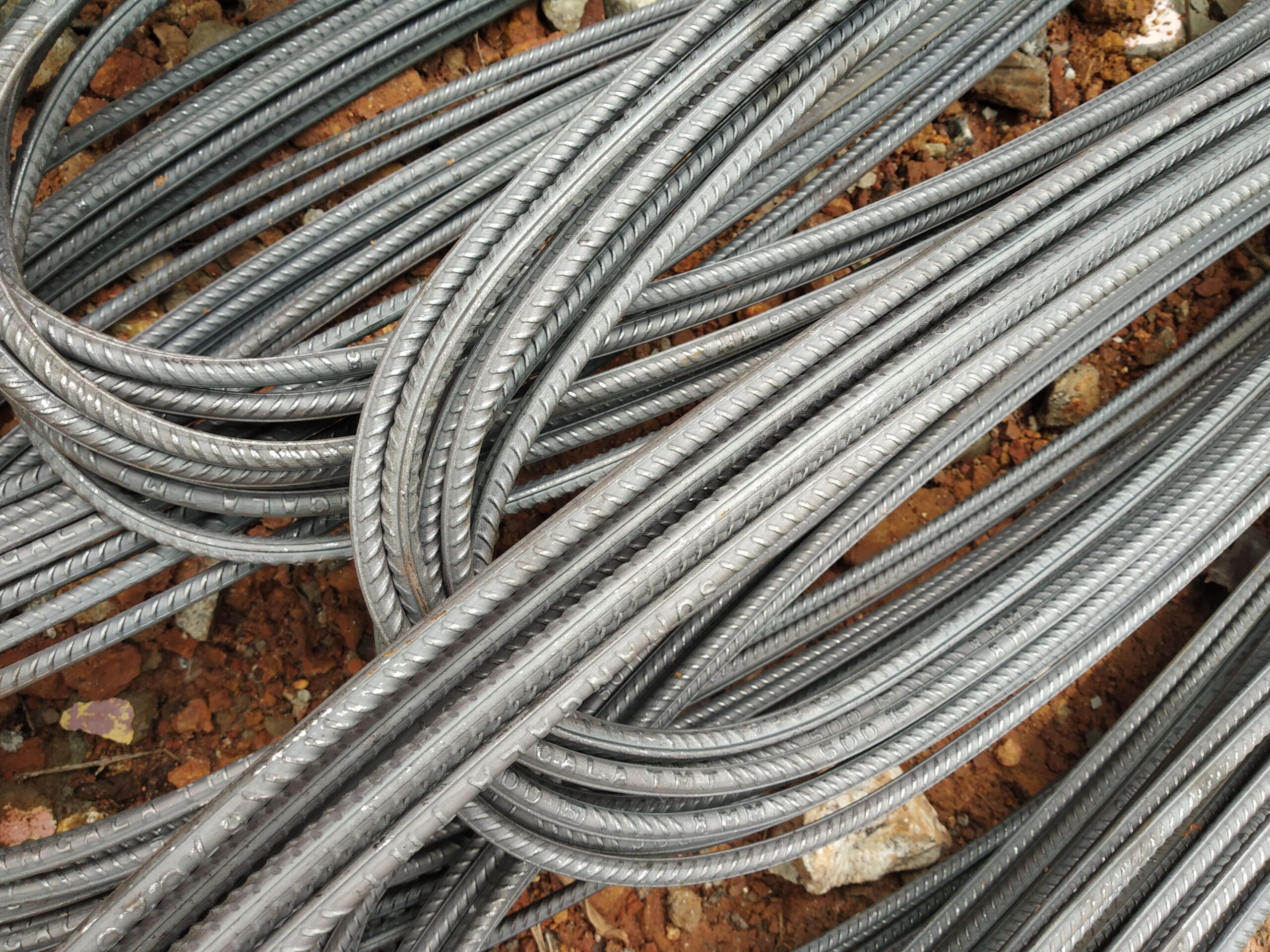
Rebar for Pad & Strip Footings: Sizes, Detailing & Quantities
Practical reinforcement guidance for reinforced concrete pad footings under columns and strip footings under walls — typical bar sizes, spacing, concrete cover and quantity estimating to DIN 488 and Eurocode 2.
Structural Role of Footing Reinforcement
Pad footings transfer concentrated column loads to the ground; strip footings spread wall loads along a continuous base. In both cases, the footing acts as an inverted cantilever: soil bearing pressure acts upward across the plan, inducing bending moments that put the bottom of the footing in tension. Reinforcement — placed near the bottom face — resists this tension and provides the flexural capacity needed to prevent punching or bending failure.
Punching shear around the column base is also critical in pad footings; where the depth-to-projection ratio is small, additional shear reinforcement (links or bent-up bars) may be required. Strip footings additionally need longitudinal bars to distribute loads and resist differential settlement along the length of the wall.
B500B (DIN 488, EN 10080) is the standard grade for footing reinforcement in German and EU construction practice. Its 500 MPa yield strength and high ductility (k ≥ 1.08, Agt ≥ 5.0 %) satisfy Eurocode 2 requirements for foundation elements. Exposure class for footings in direct soil contact is typically XC2 or higher, requiring minimum 40 mm concrete cover.
Typical Bar Sizes and Spacing for Pad Footings
Pad footing reinforcement runs in a two-way grid across the plan area. Common bar diameters and spacing:
| Diameter (mm) | Weight (kg/m) | Section (mm²) | Typical footing application |
|---|---|---|---|
| 10 | 0.617 | 78.5 | Small pad footings, low column loads, light structures |
| 12 | 0.888 | 113 | Residential pad footings, 250–600 kN column loads |
| 16 | 1.58 | 201 | Commercial footings, medium column loads |
| 20 | 2.47 | 314 | Heavy column footings, multi-storey structures |
| 25 | 3.85 | 491 | Large pad footings, heavily loaded columns |
| 32 | 6.31 | 804 | Very heavily loaded foundation pads |
Typical bar spacing for the bottom mat in pad footings is 150–200 mm both ways for residential/light commercial applications, reducing to 100–150 mm for heavier loads. The projection of the footing beyond the column face determines the moment arm and hence required steel area — a larger projection with a given thickness demands more reinforcement.
Strip Footing Reinforcement
Strip footings under load-bearing walls carry a more uniform pressure distribution but still require transverse bars to span between the wall and the footing edges (the cantilever action) and longitudinal bars to resist bending along the wall length due to variable soil conditions or point loads.
- Transverse bars: Typically 10–16 mm at 150–200 mm centres, spanning across the footing width.
- Longitudinal bars: Typically 4–6 bars of 12–20 mm along the full length at top and bottom, with links at regular intervals to maintain position and resist any torsion.
- Minimum reinforcement: Eurocode 2 §9.8.2.1 sets minimum As of 0.0015 × b × d (where b is footing width and d is effective depth) in each direction.
Concrete Cover Requirements for Footings
Footings in direct contact with soil fall into exposure class XC2 (permanently wet or in contact with non-aggressive soil) as a minimum; aggressive soil or groundwater may require XA classification. Minimum nominal cover (cnom) for footings:
- XC2 with blinding concrete: 40 mm cnom to bottom steel (sometimes 35 mm with a well-specified blinding layer)
- XC2 without blinding (directly on earth): 75 mm cnom is commonly specified to account for the rough and potentially contaminated surface
- XA (chemically aggressive ground, e.g. sulfate-bearing soil): Additional cover and/or sulfate-resisting concrete specified by the engineer
Footing reinforcement is placed on plastic spacers (chairs) to maintain the specified cover. We supply compatible rebar spacers and accessories for this purpose.
Estimating Footing Rebar Quantities for Procurement
For a pad footing take-off: count the number of bars in each direction (footing width ÷ spacing + 1), multiply by bar length (footing dimension + anchorage extensions), then apply unit weight (kg/m = d² × 0.00617). Add top steel if specified, plus any column starter bars. Strip footing estimation follows the same logic per linear metre, then multiplied by total wall length.
All export orders of footing rebar are supplied with EN 10204 3.1 Mill Test Certificate, CE Declaration of Performance, Certificate of Origin and seaworthy packing. See also: Foundations & Piling applications guide, Rebar for RC Columns, and Rebar for Retaining Walls.
Frequently Asked Questions — Footing Rebar
Why do pad footings need reinforcement if the footing is in compression?
What concrete cover is required for rebar in strip footings?
Should I use B500B or plain round bars for footing reinforcement?
How much does column starter bar length affect footing depth?
What is the minimum reinforcement ratio for a reinforced concrete footing?
Source German-Standard Rebar with Full Export Documentation
Tell us your footing schedule, bar diameters and destination port — we’ll respond with a detailed quotation including MTC and logistics.