Welded Mesh Lap Requirements
Welded mesh lap requirements govern how two adjacent sheets of reinforcing mesh must overlap to achieve continuity of the reinforcement across a joint. Getting the lap length and arrangement correct is essential for slab performance. This guide covers DIN 488-4 and Eurocode 2 lap rules for welded fabric, panel dimensions, and sourcing DIN 488-compliant mesh with full export documentation.
What Is Welded Reinforcing Mesh?
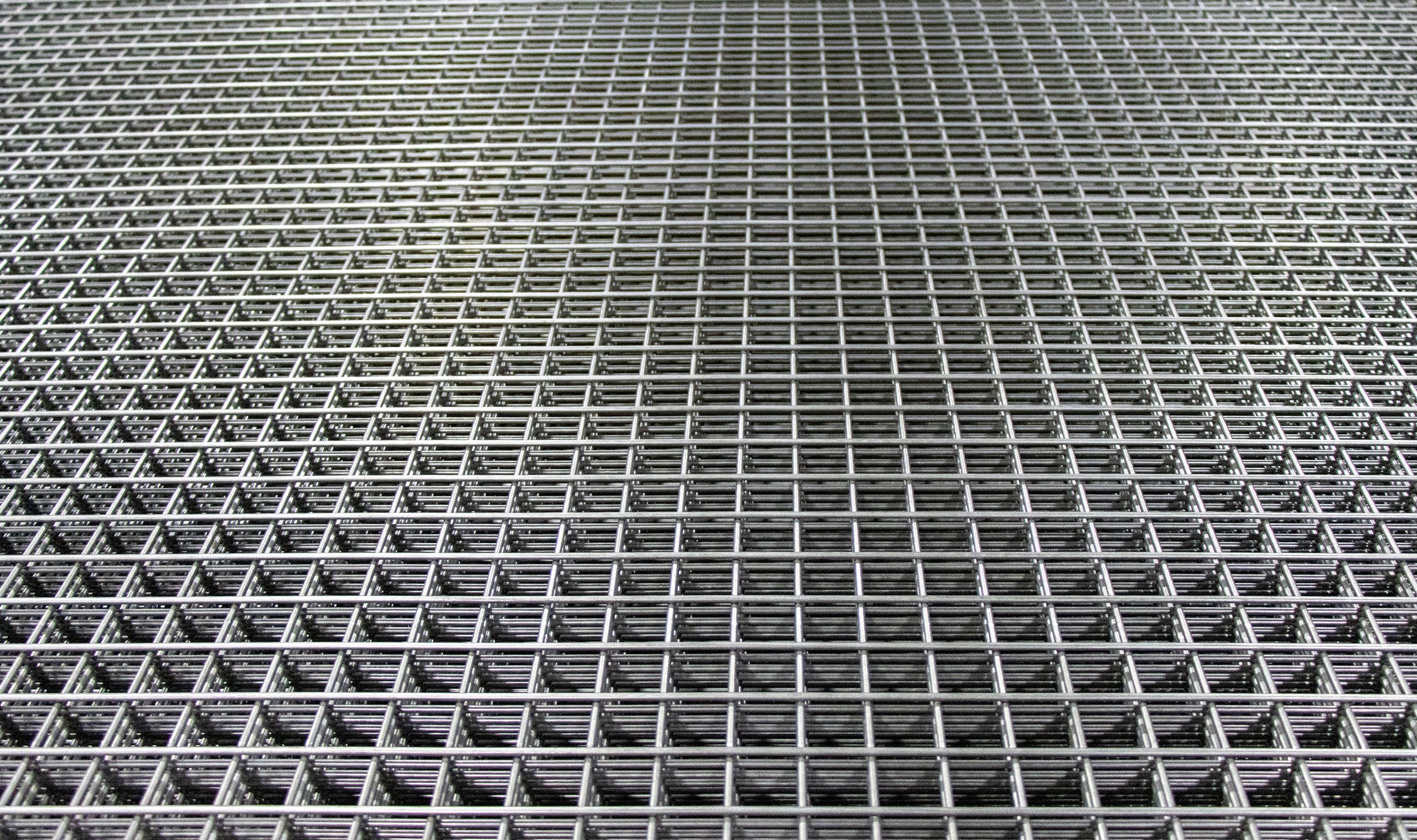
Welded reinforcing mesh (also called welded fabric or, in German, Betonstahlmatte) consists of a grid of B500A or B500B steel bars welded at every intersection to form a flat sheet. It is widely used as reinforcement in ground-bearing and elevated slabs, wall panels, road and airport pavements, and precast elements, because it greatly speeds installation compared with placing individual bars.
Standard panels in Germany comply with DIN 488 Part 4, which defines mesh types (Q-Matten — square grid, and R-Matten — rectangular grid), wire diameters, spacing, and weld quality. The most common standard panel size in Europe is 6.0 m × 2.3 m, though bespoke widths and lengths are available for project-specific layouts. The wire diameter range covered by DIN 488-4 is 4–16 mm, in both B500A and B500B grade.
Why Lapping Is Required
A structural slab is typically larger than one mesh panel. Where panels end and a new panel begins, the reinforcement must be continuous — otherwise there is a break in the tensile steel that the design relies on. This continuity is achieved by overlapping the two panels (the “lap”) by a defined length so that the forces transfer from one panel to the next through bond with the surrounding concrete.
In welded mesh, the transfer mechanism differs slightly from loose bar: the welded cross-wires act as mechanical anchors that improve bond efficiency, allowing shorter lap lengths than would be required for plain round bars of the same diameter. Eurocode 2 and DIN 488-4 both account for this.
Lap Length Rules Under DIN 488-4 and Eurocode 2
For welded fabric, Eurocode 2 clause 8.7.5 provides specific lap rules. The basic principle is the same as for individual bars — the lap length l₀ must allow sufficient bond length — but the presence of transverse welded wires improves the anchorage so a factor α₃ (which accounts for transverse reinforcement) typically takes a favourable value.
Key rules from EC2 clause 8.7.5 for lapped welded mesh:
- At least two welded cross-wires must lie within the lap length on each side of the joint.
- The spacing of the cross-wires in the lap zone must not exceed 100 mm (or 8× the main wire diameter, whichever is less) to be counted as transverse reinforcement improving bond.
- The minimum lap length l₀,min for welded mesh is max(0.3 × l₀; 200 mm; 20 × wire diameter).
- Where more than 50 % of the main steel is lapped in one cross-section, the lap length must be multiplied by α₆ = 1.4.
DIN 488-4 Annex A provides tabulated minimum lap lengths for standard mesh types in the common concrete strength classes (C20/25, C25/30, C30/37) under good bond conditions. For B500A mesh (the most common grade for flat slabs), these typically work out to 25–35× the wire diameter for tension laps in C25/30, significantly less than the 40–50× required for individual B500B bars.
Standard Lap Lengths by Wire Diameter
| Wire dia (mm) | Weight (kg/m² — sq. mesh 150×150) | Approx. tension lap (mm) C25/30, good bond | Min. cross-wires in lap |
|---|---|---|---|
| 6 | ~2.22 | 200 (controlled by minimum) | 2 |
| 8 | ~3.95 | 250–280 | 2 |
| 10 | ~6.17 | 320–350 | 2 |
| 12 | ~8.88 | 380–420 | 2 |
| 14 | ~12.1 | 440–480 | 2 |
| 16 | ~15.8 | 500–560 | 2 |
Indicative values for square mesh at 150 mm pitch, B500A, C25/30, good bond, structural class S4. Always verify against the structural engineer’s design and the applicable National Annex. Weight per m² is for mesh with the same diameter in both directions at 150 mm centres.
Lap Arrangement in Practice
How the lap is arranged — side-by-side or one panel on top of another — affects the slab thickness, cover to the lower layer, and the structural depth. Two main configurations are used:
- Side lap (edge-to-edge): The two panels meet edge-to-edge and overlap by the specified length. The total mesh assembly remains within the original slab depth. This is the more common arrangement for the main reinforcement direction.
- End lap (head-to-head): Panels overlap at their ends in the secondary reinforcement direction. Same lap length rules apply.
The critical practical point: the lap must be tied with tying wire at a minimum of every second wire intersection within the overlap zone to keep the panels from shifting during concrete placement. The designer may specify where laps must be located — typically away from maximum moment zones (mid-span for simply supported, or hogging-moment zones for continuous slabs).
Sourcing DIN 488 Mesh with Full Export Documentation
For export projects requiring DIN 488-4 or EN 10080 compliant welded mesh, the documentation chain is the same as for loose bar: a Mill Test Certificate (EN 10204 3.1) covering the wire heats, the mesh manufacturing record confirming weld quality, and, for export, a Certificate of Origin and packing list. Steel Rebar Germany supplies standard Q and R mesh panels in B500A and B500B, as well as bespoke-size panels for special project layouts. See our welded mesh product page and our guide on tying wire for rebar fixing for the accessories. Ready to specify? Visit our quote page.
Frequently Asked Questions
Technical answers on welded mesh lap requirements for procurement and engineering teams.
How many cross-wires must be included in a welded mesh lap?
Is the lap length for welded mesh the same as for individual bars?
Where should mesh laps be positioned in a slab?
What is the difference between a Q-mat and an R-mat in DIN 488-4?
Does Steel Rebar Germany supply bespoke mesh panel sizes for export?
Source German-standard rebar with full export documentation
Tell us your specification and destination port — we’ll respond with a detailed quotation.