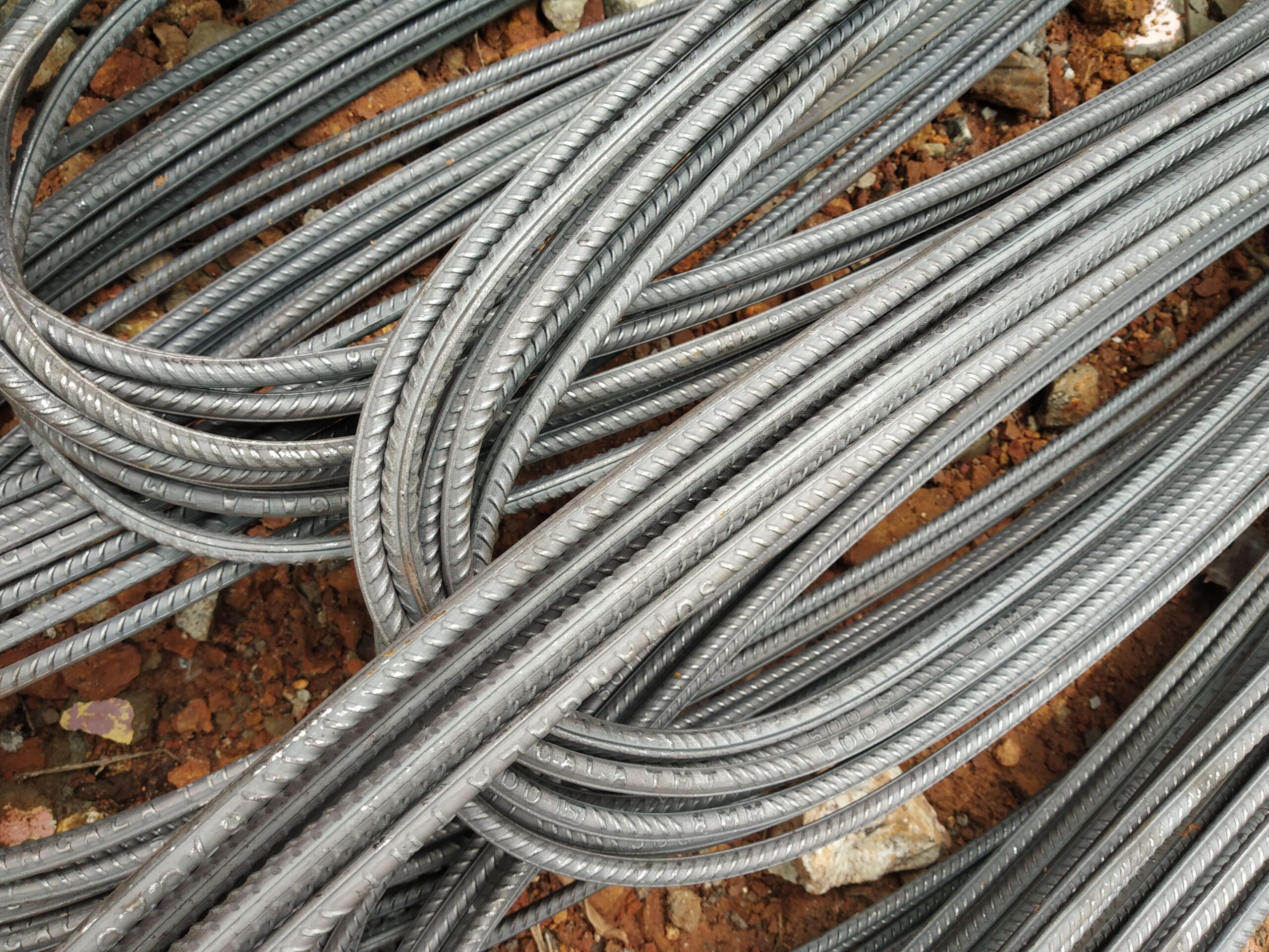
Rebar Anchorage Length to Eurocode 2: Calculation Guide & Worked Example
Anchorage length determines how far reinforcing bar must extend into concrete to transfer its full design force safely. This guide explains the Eurocode 2 method, the variables that matter, and how to interpret results — for engineers and informed procurement professionals sourcing DIN 488 / EN 10080 rebar.
What Is Rebar Anchorage Length?
Rebar anchorage length — also called the basic anchorage length (lb,rqd) — is the minimum straight embedment depth needed for a reinforcing bar to develop its full tensile or compressive design force within concrete without pulling out. It is governed by the bond stress between the bar’s ribbed surface and the surrounding concrete matrix.
In the Eurocode 2 framework (EN 1992-1-1 §8.4), anchorage requirements apply whenever a bar force must be transferred at a support, at a lap splice, or at a change in section. Getting this length right affects structural integrity; under-anchored bars can lead to premature pull-out failure, which is brittle and catastrophic.
The rebar grade supplied matters directly here: B500B (high ductility) and B500C (seismic) bars achieve higher design bond stresses than lower-grade bars, and the bar diameter is the most influential single variable in the anchorage formula.
The Eurocode 2 Basic Anchorage Length Formula
EN 1992-1-1 Clause 8.4.3 gives the required basic anchorage length as:
lb,rqd = (φ / 4) × (σsd / fbd)
- φ — bar diameter (mm)
- σsd — design stress in the bar at the anchorage point (MPa); often taken as fyd = fyk / γs = 500 / 1.15 ≈ 435 MPa for B500 steel
- fbd — ultimate bond stress (MPa) = 2.25 · η1 · η2 · fctd
Where fctd is the design tensile strength of concrete = αct · fctk,0.05 / γc. The coefficients η1 and η2 account for bar position during casting (good or poor bond conditions) and bar diameter respectively (η2 = 1.0 for φ ≤ 32 mm; 132 − φ / 100 for φ > 32 mm).
The design anchorage length lbd then applies up to five reduction coefficients (α1 through α5) for bar shape, concrete cover, transverse reinforcement and transverse pressure. The product α1 · α3 · α5 ≥ 0.7 applies as a lower bound.
Bond Stress by Concrete Grade
The table below shows indicative ultimate bond stress fbd values for ribbed bars in good bond conditions (η1 = 1.0, φ ≤ 32 mm, γc = 1.5, αct = 1.0) across common concrete grades. These are starting-point values; always verify with project-specific concrete data.
| Concrete class | fck (MPa) | fctk,0.05 (MPa) | fctd (MPa) | fbd (MPa) |
|---|---|---|---|---|
| C20/25 | 20 | 1.5 | 1.00 | 2.25 |
| C25/30 | 25 | 1.8 | 1.20 | 2.70 |
| C30/37 | 30 | 2.0 | 1.33 | 3.00 |
| C35/45 | 35 | 2.2 | 1.47 | 3.30 |
| C40/50 | 40 | 2.5 | 1.67 | 3.75 |
Worked Example: 16 mm B500B Bar in C25/30
Consider a 16 mm B500B bar anchored in C25/30 concrete, good bond conditions, no special transverse reinforcement or pressure.
- σsd = 435 MPa (full yield design stress)
- fbd = 2.70 MPa (from table above)
- lb,rqd = (16 / 4) × (435 / 2.70) = 4.0 × 161.1 = 644 mm
- With no reduction coefficients applied (conservative): lbd = 644 mm, subject to a minimum of max(0.3 · lb,rqd; 10φ; 100 mm) = max(193; 160; 100) = 193 mm — so the basic value governs at 644 mm.
- If a standard hook (α1 = 0.7 for tension, curved bar) is used: lbd = 0.7 × 644 = 451 mm.
This illustrates why hooks and bends — available as cut-and-bend service shapes to DIN 488 codes — can meaningfully reduce congestion at supports and pile caps.
Key Variables That Increase Anchorage Demand
- Larger bar diameter — lb,rqd scales linearly with φ; a 32 mm bar needs twice the length of a 16 mm bar, all else equal.
- Lower concrete strength — C20/25 gives ~25 % less fbd than C30/37, increasing required length proportionally.
- Poor bond position — bars cast in the upper zone of a deep pour (more than 300 mm of concrete below) attract η1 = 0.7, increasing lb,rqd by ~43 %.
- High bar stress — if σsd < fyd, the required length reduces proportionally (useful at laps where bars are not fully stressed).
- Seismic detailing (DCM/DCH) — EN 1998-1 imposes additional multipliers on anchorage and lap lengths; B500C grade is typically specified.
Anchorage for Common Bar Diameters (Indicative, C25/30, Good Bond)
| Diameter φ (mm) | Weight (kg/m) | lb,rqd straight (mm) | lbd with hook α₁=0.7 (mm) |
|---|---|---|---|
| 10 | 0.617 | 403 | 282 |
| 12 | 0.888 | 483 | 338 |
| 16 | 1.58 | 644 | 451 |
| 20 | 2.47 | 806 | 564 |
| 25 | 3.85 | 1007 | 705 |
| 32 | 6.31 | 1289 | 902 |
See also: Rebar Spacing Rules and Concrete Cover Requirements for the complementary detailing parameters.
Frequently Asked Questions — Rebar Anchorage Length
What is the difference between basic anchorage length and design anchorage length?
Can I use hooks to reduce anchorage length at pile caps or beam ends?
How does bar grade affect anchorage? Is B500B better than B500A?
Does anchorage length change for compression bars?
What export documentation confirms the rebar meets EN 10080 bond requirements?
Source German-standard rebar with full export documentation
Tell us your specification and destination port — we’ll respond with a detailed quotation.