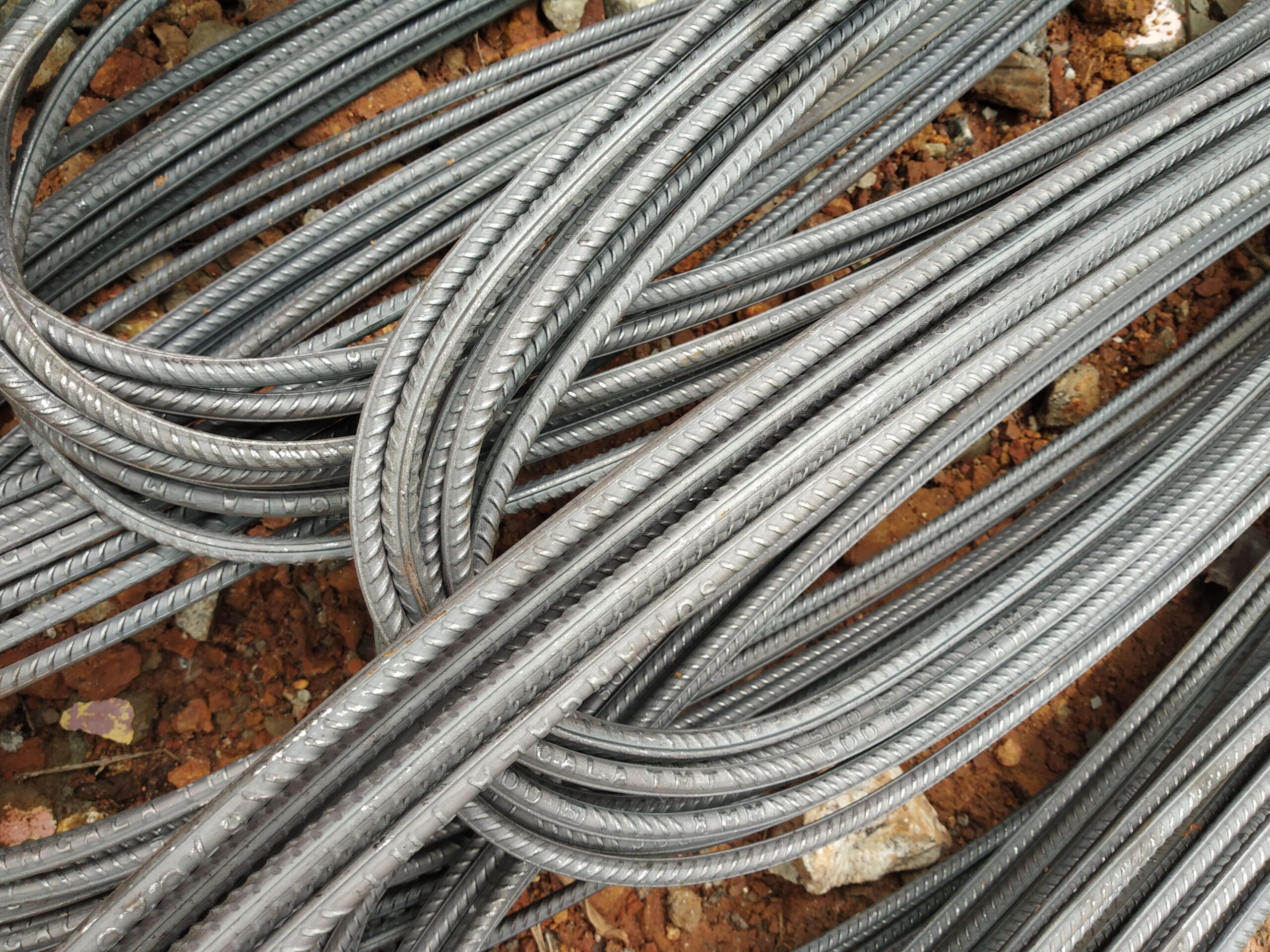
Rebar Development Length Explained
A clear explainer on anchorage and development length for reinforcing steel — with a worked example, reference table, and practical procurement guidance for DIN 488 / EN 10080 B500B rebar.
Rebar development length — the minimum embedded length required for a reinforcing bar to transfer its full design force into the surrounding concrete — is one of the most fundamental concepts in reinforced concrete design. Get it wrong and the bar simply pulls out before yielding; get it right and the steel and concrete act as the composite system the designer intended. This article explains the concept clearly, walks through a worked example using Eurocode 2 (EN 1992-1-1) and DIN 488 B500B rebar, and provides a ready-reference table for common bar sizes. This is general educational guidance — all structural designs must be verified by a licensed engineer to the applicable national code and national annex.
Rebar Development Length: What It Is and Why It Matters
When a reinforcing bar is embedded in concrete, bond stress develops at the interface between the bar’s ribbed surface and the surrounding cement paste. This bond stress — distributed over the embedded length — allows the bar to build up tensile (or compressive) force from zero at its free end to its full design value at the point of peak stress. The basic anchorage length (lb,rqd) is the straight embedment needed to develop the bar’s full design yield force fyd under a specified bond stress fbd.
The design anchorage length lbd adjusts lb,rqd by factors (α1–α5) that account for bar shape (hooks reduce required straight length), concrete cover, transverse reinforcement, and bar pressure. The lap length l0 — needed when two bars overlap to join — derives from lbd multiplied by an additional factor α6 (1.0–1.5) that accounts for what proportion of bars are lapped at the same section.
The Eurocode 2 Formula (EN 1992-1-1 Clause 8.4)
The basic required anchorage length for a bar of diameter φ is:
lb,rqd = (φ / 4) × (fyd / fbd)
Where:
- φ = bar diameter (mm)
- fyd = design yield strength of the bar = fyk / γs = 500 / 1.15 ≈ 434 MPa for B500B
- fbd = design bond strength = 2.25 × η1 × η2 × fctd
- η1 = bond condition factor: 1.0 for “good” bond (bars in bottom of pour, or inclined ≥ 45°), 0.7 for “poor” bond (top bars in sections > 250 mm deep, or bars cast horizontally with > 300 mm concrete below)
- η2 = bar diameter factor: 1.0 for φ ≤ 32 mm; (132 − φ)/100 for φ > 32 mm
- fctd = design concrete tensile strength = αct × fctk,0.05 / γc
The design anchorage length lbd = α1 × α2 × α3 × α4 × α5 × lb,rqd ≥ lb,min, where lb,min = max(0.3 × lb,rqd; 10φ; 100 mm) for tension anchorage.
Worked Example: T16 B500B in C25/30 Concrete (Good Bond)
Bar: φ = 16 mm, B500B (fyk = 500 MPa). Concrete: C25/30 (fck = 25 MPa). Good bond condition (bottom bar). Straight bar (α1 = 1.0), adequate cover (α2 ≈ 1.0), no transverse pressure (α5 = 1.0).
- fyd = 500 / 1.15 = 434.8 MPa
- fctk,0.05 for C25/30 = 1.8 MPa (EN 1992-1-1 Table 3.1); fctd = 1.0 × 1.8 / 1.5 = 1.20 MPa
- fbd = 2.25 × 1.0 × 1.0 × 1.20 = 2.70 MPa
- lb,rqd = (16 / 4) × (434.8 / 2.70) = 4 × 161.0 = 644 mm ≈ 640 mm
- With α factors all ≈ 1.0: lbd ≈ 640 mm (40 × φ)
- Lap length (50% bars lapped, α6 = 1.4): l0 ≈ 1.4 × 640 = 896 mm ≈ 900 mm
This is a typical result: T16 bars in C25/30 concrete require roughly 640 mm straight anchorage and 900 mm laps when 50% of bars are joined at the same cross-section. Using stronger concrete (e.g., C30/37) reduces these values proportionally — fbd rises to approximately 3.0 MPa, cutting lb,rqd to about 580 mm.
Development Length Reference Table (B500B, Good Bond, C25/30)
Indicative straight anchorage lengths lb,rqd for B500B bars in C25/30 concrete, good bond, all α-factors = 1.0. Values calculated from the EN 1992-1-1 formula above.
| Bar dia φ (mm) | Weight (kg/m) | Section (mm²) | lb,rqd (mm) | lb,rqd / φ | Typical lap (50% lapped, mm) |
|---|---|---|---|---|---|
| 8 | 0.395 | 50.3 | 320 | 40 | 450 |
| 10 | 0.617 | 78.5 | 400 | 40 | 560 |
| 12 | 0.888 | 113 | 480 | 40 | 670 |
| 16 | 1.58 | 201 | 640 | 40 | 900 |
| 20 | 2.47 | 314 | 800 | 40 | 1120 |
| 25 | 3.85 | 491 | 1000 | 40 | 1400 |
| 32 | 6.31 | 804 | 1280 | 40 | 1790 |
| 40 | 9.86 | 1257 | 1600 | 40 | 2240 |
All values indicative for C25/30 concrete, good bond, straight bars, α-factors = 1.0. For poor bond conditions (top bars), divide fbd by η1 = 0.7, increasing lb,rqd by ~43%. Always verify with project-specific calculations.
Hooks, Bends, and Mechanical Anchorage
A standard 90° or 180° hook reduces the required straight embedment by applying factor α1 = 0.7 to lb,rqd (provided minimum cover to the bent portion ≥ 3φ). This means a T16 bar with a standard hook in C25/30 concrete requires only about 450 mm of straight embedment beyond the bend — useful in tight column or beam-end anchorage zones.
Mechanical end anchorages (plates, anchored heads) can further reduce or eliminate the straight development length requirement, subject to manufacturer test data and design engineer approval. For applications where development length is the critical constraint — dense pile-cap reinforcement, precast connection zones — mechanical couplers provide an alternative that eliminates lap lengths entirely.
Development Length vs Lap Length: Key Differences
- Development length (anchorage length): applies at bar ends — at supports, at cut-off points mid-span, and into connections. The bar starts from zero force and builds to the required design force over the embedded length.
- Lap length: applies where two bars overlap to transfer force from one bar to the next. Lap length = α6 × lbd. The α6 factor (1.0–1.5) penalises concentrating too many laps at the same cross-section, which increases local bond demand and cracking risk.
- Stagger laps: EN 1992-1-1 recommends that no more than 50% of bars be lapped at any one cross-section (a6 = 1.4 applies when 50% are lapped; 1.5 when 100% are lapped in the same zone).
For procurement purposes, development and lap lengths determine the minimum bar order length required. When mill lengths of 6–12 m are used for elements longer than a single bar, lap lengths add directly to the total steel tonnage — typically 10–15% on top of the net structural requirement.
Sourcing the Right Bar for Your Development Length Requirements
Development length is sensitive to bar diameter: larger bars require proportionally longer embedment. Where headroom in a connection is limited, specifying a greater number of smaller bars (same total steel area, shorter individual development length) can be the design solution. We supply B500B straight bars in diameters 8–40 mm and lengths up to 18 m, with EN 10204 3.1 Mill Test Certificate confirming the mechanical properties (fyk, fuk, Agt) that feed directly into fyd and development length calculations. Cut-and-bend services to DIN 488 shape codes produce hooks and bends to the exact geometry your engineer specifies. For full export documentation and logistics see our export and delivery page.
Frequently Asked Questions
What is rebar development length?
How does bar diameter affect development length?
What is the difference between development length and lap length?
Does using a hook or bend reduce development length?
How does concrete strength affect development length?
Source German-standard rebar with full export documentation
Tell us your bar sizes, grade, and destination port — we’ll respond with a detailed quotation including Mill Test Certificate.