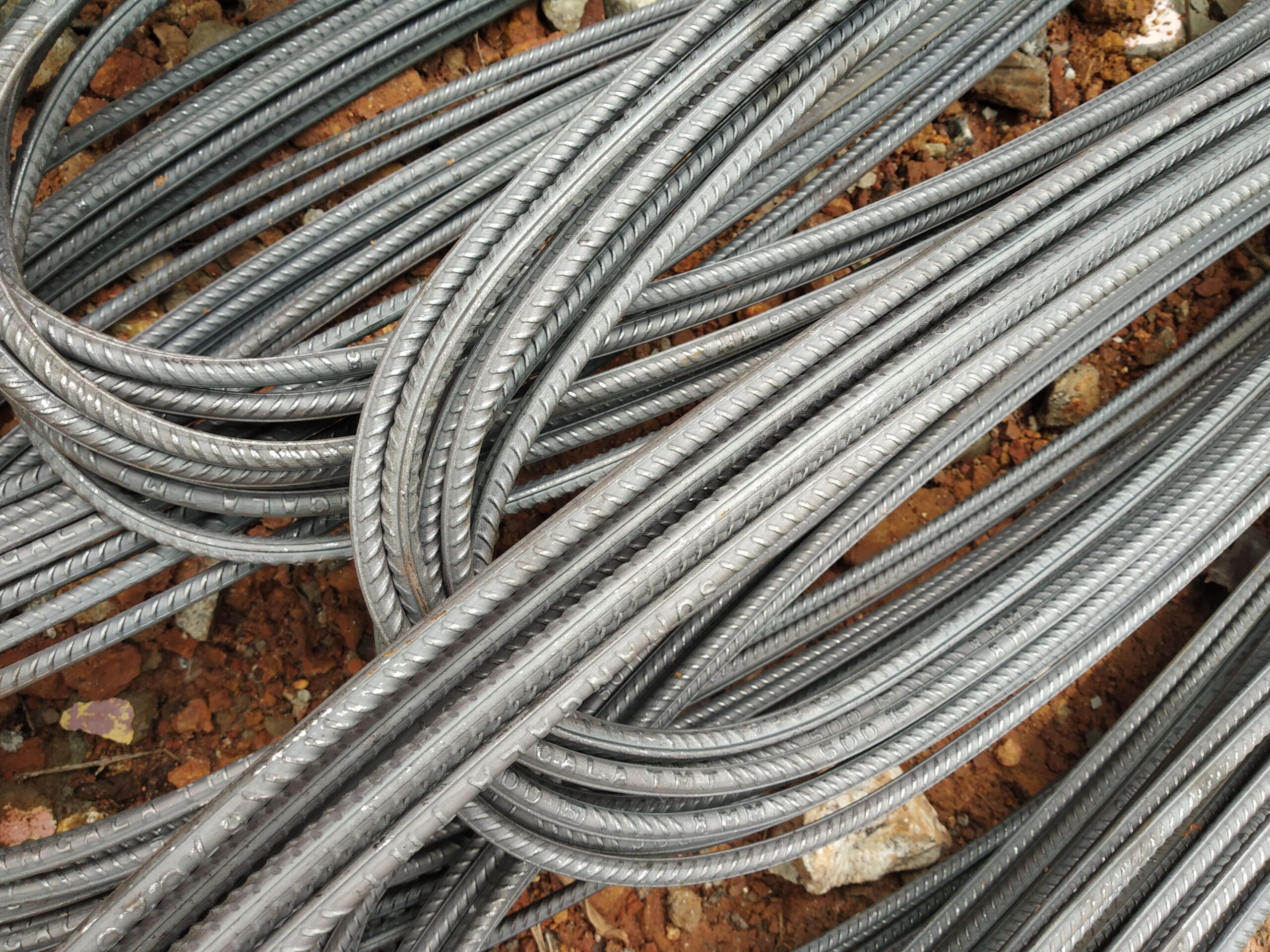
What Size Rebar for a Concrete Water Tank?
Practical bar-size, spacing, and cover guidance for reinforced concrete water tanks — using B500B rebar to DIN 488 / EN 10080. Indicative figures only; confirm with a structural engineer experienced in liquid-retaining structures.
Why Rebar Selection Is Critical in Concrete Water Tanks
Reinforced concrete water tanks present unique design challenges compared to standard structural elements. The wall must resist hydrostatic pressure from the liquid inside, while the base slab acts as a mat under water load. Critically, liquid-retaining structures must be designed for crack width control — not just ultimate strength — because cracks wider than approximately 0.2 mm (the limit in EN 1992-3 for potable water tanks) can allow leakage and accelerate reinforcement corrosion.
Because crack control in tension governs the reinforcement area requirement in many water tank walls (rather than bending strength), the result is often a higher steel ratio at smaller bar diameters and tighter spacing than a structural calculation alone would indicate. Closer bar spacing reduces individual crack widths effectively.
B500B (hot-rolled, 500 MPa min yield, Agt ≥ 5.0%, k ≥ 1.08 per DIN 488 / EN 10080) is the standard grade. For potable water contact, no special alloy or coating is typically required for the reinforcement in concrete structures — the alkaline concrete environment provides passivation — but adequate cover and crack-width control are essential.
All figures below are indicative and for preliminary planning only. A licensed structural engineer with experience in liquid-retaining structures must design and verify all tank reinforcement.
Typical Rebar Sizes for Concrete Water Tank Walls
Tank walls in direct contact with water experience hoop tension (in circular tanks) or combined bending and direct tension (in rectangular tanks). Closer bar spacing is preferred for crack control. Typical indicative ranges:
| Tank Type / Wall Height | Wall Thickness | Typical Bar Dia. | Typical Spacing (each face) |
|---|---|---|---|
| Small domestic tank (wall H ≤ 2 m) | 150–200 mm | 10–12 mm | 150–200 mm both directions |
| Medium rectangular tank (H 2–4 m) | 200–300 mm | 12–16 mm | 125–175 mm both directions |
| Large rectangular / industrial tank (H 4–6 m) | 300–400 mm | 16–20 mm | 100–150 mm both directions |
| Circular prestressed tank wall | 200–350 mm | 10–16 mm vertical + hoop bars | 100–150 mm vertical; hoop designed separately |
Crack Width Control: Why Spacing Matters More Than Diameter
EN 1992-1-1 clause 7.3 and EN 1992-3 (liquid-retaining structures) limit crack widths based on tightness class. For a potable water tank (tightness class 2), wk,max = 0.2 mm. The maximum bar spacing for direct crack width control (EN 1992-1-1 Table 7.3N) at a steel stress of approximately 240 MPa (typical service stress in a water-retaining wall) is approximately:
- ø10 mm bars: max spacing ≈ 300 mm
- ø12 mm bars: max spacing ≈ 275 mm
- ø16 mm bars: max spacing ≈ 200 mm
- ø20 mm bars: max spacing ≈ 150 mm
In practice, engineers often specify ø12 or ø16 at 150 mm in both faces to satisfy both strength and crack-width requirements simultaneously.
| Diameter (mm) | Weight (kg/m) | Cross-section (mm²) | Steel area at 150 mm spacing (mm²/m) |
|---|---|---|---|
| 10 | 0.617 | 78.5 | 523 |
| 12 | 0.888 | 113 | 753 |
| 16 | 1.58 | 201 | 1,340 |
| 20 | 2.47 | 314 | 2,093 |
Concrete Cover Requirements for Water Tanks
Reinforcement in liquid-retaining structures is in an XC4 (cyclically wet and dry) or XD1/XD2 environment. Nominal cover for the internal face of the tank (in contact with water) is typically:
- Internal face (water contact): 40–50 mm nominal cover to outer bar
- External face (buried or exposed to soil): 40–75 mm depending on exposure
- Base slab (on blinding): 40–50 mm to bottom mat
Higher cover and denser rebar combined with water-tight concrete (w/c ratio ≤ 0.45–0.50) are the primary defences against leakage.
Indicative Material Estimate (Preliminary Only)
Consider a rectangular water tank: 5 m × 4 m plan, 3 m wall height, wall thickness 250 mm, ø12 @ 150 mm in both faces both directions.
- Total wall perimeter: 2 × (5 + 4) = 18 m; wall area: 18 × 3 = 54 m²
- Bars per metre (horizontal): 1000/150 ≈ 6.67 bars/m height × 3 m = 20 bar runs × 18 m length = 360 m horizontal bar per face
- Bars per metre (vertical): 6.67 bars/m plan × 18 m perimeter = 120 bar runs × 3 m height = 360 m vertical bar per face
- Total bar length (both faces, walls): 4 × 360 m = 1,440 m ø12
- Indicative weight (walls only): 1,440 × 0.888 ≈ 1,279 kg
- Base slab (5 × 4 m, ø12 @ 150 mm, top + bottom, both directions): approx. additional 540 m × 0.888 ≈ 479 kg
- Total indicative rebar for tank: ≈ 1,760 kg (excluding laps and anchorages)
We supply B500B straight bar in stock lengths from 6–12 m and can supply cut-to-length bar to your schedule. For large water infrastructure projects, we export worldwide with full documentation.
Frequently Asked Questions — Rebar for Concrete Water Tanks
What rebar grade is best for a concrete water tank?
Why are smaller bar diameters at closer spacing used in water tanks?
What concrete cover is required on the water-contact face of a tank?
Is circular or rectangular better for reinforced concrete water tanks?
Can Steel Rebar Germany supply rebar for water infrastructure projects?
Source German-standard rebar with full export documentation
Tell us your water tank specification, destination port, and required standards — we’ll respond with a detailed quotation including MTC and CE documentation.