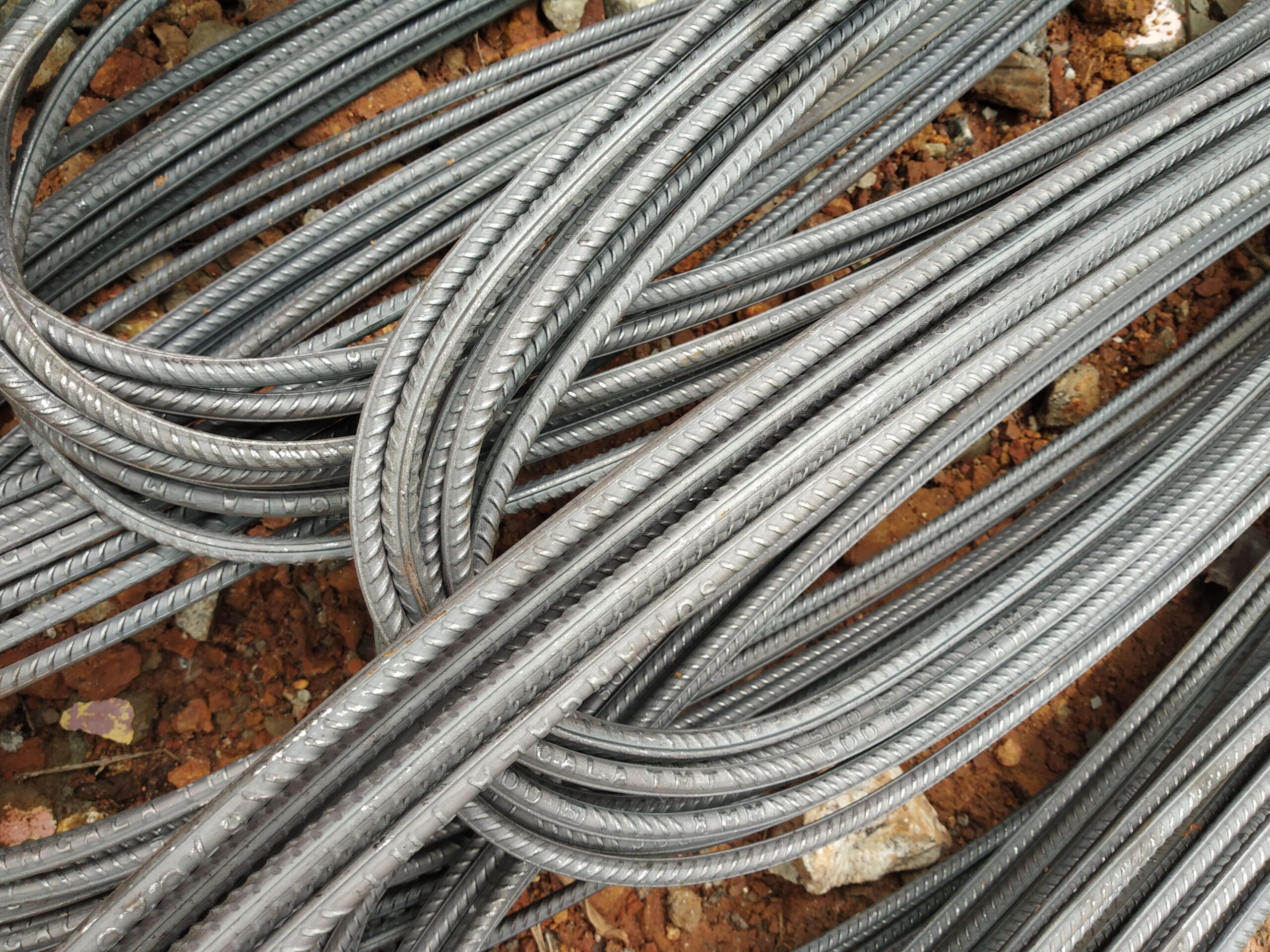
Why Is Rebar Ribbed?
The deformed surface of reinforcing steel — those transverse ribs and longitudinal fins — is not cosmetic. Rib geometry governs the bond between steel and concrete, and EN 10080 specifies exactly how it must be measured and verified.
The Problem Ribs Solve: Bond Between Steel and Concrete
Plain (smooth) steel bars embedded in concrete rely almost entirely on friction and adhesion at the steel-concrete interface to transfer tensile forces. Under load, plain bars can slip within the concrete matrix before the full tensile capacity of the bar is mobilised — a failure mode that can be sudden and without warning.
Deformed bars — universally known as rebar — solve this with a mechanical interlock. The transverse ribs press against the surrounding concrete and create bearing stress perpendicular to the bar axis. The result is a composite structural action where tensile forces are transferred into the concrete along the full development length of the bar rather than relying on adhesion alone.
Rib Geometry: What EN 10080 Specifies
EN 10080 (and its German transposition DIN 488) defines the rib geometry requirements for reinforcing steel through the concept of the relative rib area, designated fR. This dimensionless parameter is defined as:
fR = (projected rib area per unit length) / (nominal bar perimeter × bar spacing)
In plain terms, fR measures how much of the bar surface is occupied by rib projections relative to the theoretical cylinder the bar would occupy. EN 10080 sets minimum fR values that depend on bar diameter:
| Bar diameter (mm) | Min. relative rib area fR |
|---|---|
| 6 to 8 | ≥ 0.035 |
| > 8 to 12 | ≥ 0.040 |
| > 12 to 16 | ≥ 0.056 |
| > 16 | ≥ 0.065 |
These are minimum values. Higher fR generally improves bond but also influences the angle of the concrete shear cone that forms between ribs — an excessively high fR can cause splitting rather than pull-out failure. Mill designers therefore optimise rib geometry within a defined range rather than simply maximising rib height.
Rib Parameters: Height, Spacing, Angle and Inclination
Beyond fR, EN 10080 and DIN 488 prescribe additional rib dimensions to ensure consistent bond performance and to allow bars from different mills to be used interchangeably in the same structure:
- Rib height (h): the perpendicular projection of the rib above the bar core surface. Minimum heights range from approximately 0.3 mm (for 6 mm bars) to 1.5 mm (for 40 mm bars).
- Rib spacing (c): the centre-to-centre distance between adjacent transverse ribs. Maximum spacing is typically 0.7 × nominal diameter.
- Rib inclination (α): the angle between the transverse rib and the bar axis, typically 35°–75°. Ribs perpendicular to the axis (90°) maximise bearing but can concentrate splitting stresses; angled ribs offer a balance between bond and transverse cracking resistance.
- Longitudinal ribs: one or two fins running along the bar length, used partly for identification (see the related post on grade markings) and partly to improve handling.
Bond Strength and Development Length
Eurocode 2 (EN 1992-1-1) uses the concept of the basic anchorage length lb,rqd to determine how deep a bar must be embedded in concrete to develop its full design tensile stress. This length is proportional to bar diameter and design steel stress, and inversely proportional to the design bond stress fbd, which in turn depends on the concrete strength class and the bar surface type.
Deformed bars (ribbed) are classified as “high bond” bars in Eurocode 2. High bond bars attract a significantly higher fbd value than plain bars of the same diameter — typically by a factor of approximately 1.4 for C20/25 concrete, rising to around 1.6 for C30/37. In practice this means a ribbed B500B bar requires a substantially shorter development length than a smooth bar of identical cross-section, allowing engineers to design more compact structural connections and reduce concrete cover zones.
Why Rib Quality Matters for Export Procurement
When sourcing rebar internationally, the rib geometry reported on the Mill Test Certificate and the physical bar markings are the primary indicators of standard compliance. German-produced B500B bars manufactured to DIN 488 carry rolled-in rib patterns that have been verified against EN 10080 fR requirements during the mill qualification process. The CE Declaration of Performance references the rib geometry test method and confirms that the lot meets the harmonised standard.
Bars from non-certified sources may appear visually similar but lack the measured fR documentation. For project specifications that reference Eurocode 2 design tables — which assume EN 10080 high-bond geometry — using non-certified bars creates a liability gap that most structural engineers are unwilling to accept.
Further detail on B500B product specifications is available on our B500B rebar page, and export documentation requirements are covered on the export and delivery page.
Related Reading
Frequently Asked Questions
Common questions about rebar rib geometry and bond performance.
What is relative rib area (fR) and why does it matter?
Can smooth (plain) rebar still be used in concrete structures?
Do all countries use the same rib geometry requirements?
Does rib geometry affect how rebar is bent or cut?
Is higher rib area always better for bond strength?
Source German-standard rebar with full export documentation
Tell us your specification and destination port — we’ll respond with a detailed quotation.