Mill-certified reinforcing steel — BS 4449 · ASTM A615 · ISO 6935sales@steelrebargermany.deWhatsApp +49 163 1141934

Category: Applications

Reinforcing steel in real construction: foundations, infrastructure, high-rise and precast.

  • Reinforcing Steel for Manholes

    Reinforcing Steel for Manholes

    Application Guide

    Reinforcing Steel for Manholes: Bar Sizes, Arrangement, and Supply

    Manholes are access chambers built into drainage, sewer, and utility networks at depths from 1 m to over 6 m below ground. Whether cast in situ or fabricated as precast rings, their reinforcement must resist earth pressure, groundwater, traffic surcharge, and the corrosive wastewater environment inside. Steel Rebar Germany supplies B500B bar, mesh, and cut-and-bend cages to DIN 488 and EN 10080 for manhole construction worldwide.

    DIN 488 · EN 10080 Mill Test Certificate Worldwide export

    Structural Demands on Manhole Reinforcement

    A manhole is essentially a buried reinforced concrete chamber. Its walls act as retaining structures resisting lateral earth and groundwater pressure; its base slab spans between the walls and may carry water flow or act as a foundation on soft ground; its cover slab or frame ring transfers surface loads (pedestrian, vehicle, or heavy traffic) into the chamber walls. In deep manholes, the cumulative earth and surcharge pressure at the base can be considerable.

    The governing design standard in Germany and Europe is EN 1992-1-1 (Eurocode 2), supported by EN 1295-1 for buried pipeline structures and DIN EN 1671 / EN 476 for sewer system components. Precast concrete manholes are also covered by EN 1917 (concrete access chambers and inspection chambers).

    Typical Bar Sizes and Arrangement

    For in-situ rectangular or circular manholes, the reinforcement typically consists of hoop (circumferential) bars, vertical bars, and base-slab mats. Indicative values for a standard circular shaft in medium ground conditions (K0 = 0.5, no groundwater) are given below — always design to project-specific conditions.

    Manhole ElementTypical Bar DiaTypical SpacingWeight kg/m
    Shaft wall — hoop bars (outer face)Ø10–12 mm B500B150–200 mm0.617–0.888 kg/m
    Shaft wall — hoop bars (inner face)Ø8–10 mm B500B150–200 mm0.395–0.617 kg/m
    Shaft wall — vertical distribution barsØ8–10 mm B500B200–300 mm0.395–0.617 kg/m
    Base slab — main steel (both ways)Ø12–16 mm B500B150–200 mm0.888–1.58 kg/m
    Cover slab — main steelØ10–16 mm B500B150–200 mm0.617–1.58 kg/m
    Cover slab — distribution steelØ8–10 mm B500B200–250 mm0.395–0.617 kg/m
    Indicative figures only. Actual bar sizes, number of faces reinforced, and spacing must be determined by structural calculation to project-specific depth, surcharge, soil, and groundwater conditions. Always refer to the project structural engineer.

    Concrete Cover in the Wastewater Environment

    Manhole interiors are among the most corrosive environments for reinforced concrete. Biogenic sulphuric acid (BSA) attack — produced by anaerobic bacteria in the crown and upper shaft of sewers — and chemical attack from industrial effluents can rapidly degrade concrete cover and reach the reinforcement. Exposure class considerations include:

    • Soil-buried outer face (XC2 / XC4): cnom ≥ 35–40 mm; XA1–XA3 if aggressive ground chemistry.
    • Inner face — foul sewer (XA2 / XA3 chemical attack): cnom ≥ 40–50 mm; high-performance concrete (C35/45 minimum) or polymer lining to protect the substrate.
    • Cover slab — road traffic (XD1): cnom ≥ 40–45 mm in areas where de-icing salts are used.

    For aggressive foul sewers, protective coatings applied over the hardened concrete are common (epoxy, polyurea, cementitious lining). The reinforcement itself is typically standard B500B; stainless steel or epoxy-coated bar is specified only in extreme chemical conditions on the advice of the project engineer and corrosion specialist.

    Precast vs In-Situ Manholes

    Precast concrete manhole rings (to EN 1917 or DIN V 4034-1) dominate the market for standard sewer manholes up to about 1 500 mm internal diameter. The reinforcement cages for precast rings are produced by the precast manufacturer to their own engineered designs. Steel Rebar Germany supplies B500A wire rod and coil for precast manufacturers’ automated cage-winding and mesh-welding equipment.

    For non-standard, large-diameter (1 500–3 000 mm and above), or deep access chambers, in-situ construction is common. These require project-engineered reinforcement supplied as straight bar or cut-and-bend cages to DIN 488 shape codes. Large pumping station wet wells and inspection chambers on major sewer trunk mains often fall into this category.

    Supply Options from Steel Rebar Germany

    • Straight B500B bar (dia 8–32 mm, 6–18 m): for large in-situ chambers where the bar schedule varies by shaft depth increment.
    • Cut-and-bend cages: hoop rings, vertical bars, and base-slab mats bent to DIN 488 / BS 8666 shape codes and bundled by element. Reduces cage assembly time on site.
    • B500A coil (dia 6–16 mm): for precast manhole ring manufacturers supplying their own cage-forming equipment.
    • Welded mesh (B500A): flat panels suitable for base slabs and cover slabs of regular rectangular manholes where mesh can be cut to fit.

    See our cut-and-bend service, B500B bar, and B500A coil pages for full product details. For drainage infrastructure context, see also the infrastructure and bridges application page.

    Export and Documentation

    Manhole reinforcement is exported in seaworthy bundles labelled by element, diameter, and bar bending schedule reference. EN 10204 3.1 Mill Test Certificates are issued per heat and per diameter, providing full traceability. The standard export package includes a Certificate of Origin, CE Declaration of Performance under EN 10080, packing list, and commercial invoice. Containers are typically 20 ft or 40 ft; long straight bars (over 12 m) require open-top or flat-rack containers, which we can arrange on request.

    Frequently Asked Questions

    Common questions about reinforcing steel for manhole construction.

    What rebar grade is standard for in-situ reinforced concrete manholes?
    B500B (DIN 488 / EN 10080 Class B, high ductility) is the standard specification for in-situ structural manholes — shaft walls, base slabs, and cover slabs — where bending under earth pressure and traffic surcharge demands Class B ductility per Eurocode 2. B500A coil is used by precast ring manufacturers on automated cage-winding lines.
    How deep can a reinforced concrete manhole be designed?
    There is no absolute depth limit, but practical in-situ construction typically covers depths from around 1.5 m to 6–8 m. Beyond approximately 6 m, the earth pressure at the base requires heavier reinforcement and thicker walls, and segmental tunnel-lining or caisson construction may be more economic. The structural engineer designs the manhole for the specified depth, soil, and surcharge conditions.
    Is additional corrosion protection needed for rebar in foul sewers?
    Standard B500B with adequate concrete cover (cnom ≥ 40–50 mm) and a minimum concrete grade of C35/45 provides the primary corrosion barrier. In sewers subject to biogenic sulphuric acid or aggressive industrial effluent, a polymer or cementitious protective lining is applied to the hardened concrete interior face — this is the standard protective approach rather than specifying coated rebar, which is reserved for extreme exposure conditions at the project engineer’s discretion.
    Can you supply reinforcement for precast manhole rings?
    Yes. We supply B500A wire rod and coil in dia 6–16 mm to precast manufacturers whose automated equipment forms the cage. We also supply straight B500B bar and welded mesh for precast manufacturers producing bespoke or non-standard rings. Contact us via the quote form with your product specification and annual volume.
    What documentation is supplied with manhole reinforcement for export?
    Standard export documentation includes EN 10204 3.1 Mill Test Certificates (traceable to the heat), CE Declaration of Performance under EN 10080, Certificate of Origin, packing list (with grade, diameter, heat number, and bundle reference), and commercial invoice. All documents are provided in English. Country-specific import documents (e.g. EUR.1 movement certificate, legalisations) can be arranged on request.

    Source German-standard rebar with full export documentation

    Tell us your specification and destination port — we’ll respond with a detailed quotation.
    Request a Quote →
  • Rebar for Suspended & Ground Slabs: Sizes, Detailing & Quantities

    Rebar for Suspended & Ground Slabs: Sizes, Detailing & Quantities

    ✉ sales@steelrebargermany.deWhatsApp +49 163 1141934Firmenbuchnummer FN 492320 aUID ATU73443516Steel Pro Rebar Germany Gmbh — Wholesale Rebar Supplier & Exporter✉ sales@steelrebargermany.deWhatsApp +49 163 1141934Firmenbuchnummer FN 492320 aUID ATU73443516Steel Pro Rebar Germany Gmbh — Wholesale Rebar Supplier & Exporter
    Rebar Detailing Guide

    Rebar for Suspended & Ground Slabs: Sizes, Detailing & Quantities

    Practical reinforcement guidance for flat slabs and ground-bearing slabs — typical bar sizes, spacing, concrete cover, and quantity estimating using DIN 488 / EN 10080 compliant B500B rebar.

    DIN 488 · EN 10080 Mill Test Certificate Worldwide Export

    Why Slab Reinforcement Specification Matters

    Slabs are among the most material-intensive reinforced concrete elements on any project. Whether you are designing a ground-bearing industrial floor or a multi-storey suspended flat slab, choosing the right bar diameter, spacing and grade is central to both structural performance and procurement cost. This guide provides general, reference-level detailing information for international B2B buyers sourcing DIN 488-compliant rebar. It is not a substitute for project-specific structural engineering.

    The dominant grade for slab reinforcement in German and EU practice is B500B — hot-rolled, high-ductility (k ≥ 1.08, Agt ≥ 5.0 %), 500 MPa minimum yield, conforming to DIN 488 and EN 10080. For lightly loaded secondary mesh or crack-control zones, B500A (cold-rolled, normal ductility, Agt ≥ 2.5 %) is also widely used, often supplied as ready-made mesh panels.

    Typical Bar Sizes for Slab Applications

    Slab main reinforcement typically runs from 10 mm to 20 mm diameter, with 12 mm and 16 mm being the most common choices across residential, commercial and infrastructure projects. Secondary (distribution / anti-crack) bars are frequently 8 mm or 10 mm. The table below gives unit weights and cross-sections for the most relevant diameters:

    Diameter (mm)Weight (kg/m)Cross-section (mm²)Typical slab use
    80.39550.3Distribution / anti-crack bars
    100.61778.5Light slabs, mesh secondary layer
    120.888113Residential flat slabs, ground slabs
    161.58201Commercial suspended slabs, heavy ground floors
    202.47314Transfer slabs, heavily loaded podium decks
    253.85491Thick transfer plates, pile caps with slab action

    Spacing and Cover Requirements

    Eurocode 2 (EN 1992-1-1) governs design in Germany and across the EU. Key detailing principles for slabs include:

    • Main bar spacing: Typically 100 mm–200 mm centre-to-centre in each direction for two-way spanning slabs; up to 300 mm for one-way slabs under modest load.
    • Minimum concrete cover: 20 mm for internal elements (XC1 exposure class), 30–40 mm for external or aggressive environments (XC2–XC4, XD classes). Cover is measured to the outermost bar.
    • Minimum bar spacing: Not less than the maximum aggregate size + 5 mm, and not less than the bar diameter.
    • Maximum bar spacing: Eurocode 2 §9.3 limits main bar spacing to 3h or 400 mm (whichever is smaller) for slabs where h is the slab depth.
    • Two-layer arrangement: Suspended slabs carry bottom steel in the span and top steel over supports; ground slabs often use a single central layer or top-and-bottom mesh.

    For ground-bearing slabs on prepared sub-base, a damp-proof membrane (DPM) beneath the concrete reduces the moisture exposure class; minimum cover can sometimes be reduced accordingly, but local ground conditions and engineer’s specification govern.

    Estimating Rebar Quantities for Slabs

    A reliable starting point for quantity take-off uses the unit weight formula from DIN 488: kg/m = d²(mm) × 0.00617. For a practical order estimate, multiply bar weight per metre by total bar length and add a waste allowance (typically 5–8 % for standard cut-and-bend, less if pre-cut mesh panels are used).

    Example: A 200 m² ground slab, 200 mm thick, with T12 @ 150 mm both ways top and bottom. Each direction: 200 m / 0.15 = 1,334 bars × 10 m average length = 13,340 m. Four layers × 13,340 m = 53,360 m of 12 mm bar. At 0.888 kg/m that is approximately 47,400 kg (47.4 t) before waste. Real projects require a full bar bending schedule per DIN 488 or BS 8666.

    For large slab orders, standard reinforcing mesh panels (e.g. 6.0 × 2.3 m, Q-type) can significantly reduce on-site labour. We supply both loose B500B bars and mesh to DIN 488-4.

    Sourcing DIN 488-Compliant Slab Rebar for Export

    International projects targeting German or EU-standard documentation require a Mill Test Certificate (MTC) to EN 10204 3.1, which certifies the heat/cast-specific mechanical and chemical properties of each bar batch. This is a mandatory document for EU-standard projects and increasingly demanded by international project lenders and insurance underwriters.

    We supply B500B rebar in straight bars (8–40 mm, 6–18 m length) and coil form (6–16 mm) for automated processing. All export shipments include the MTC, Certificate of Origin, CE Declaration of Performance, packing list, and seaworthy bundle packaging typically in 2-tonne lifts — ready for container or break-bulk loading. Lead times and minimum order quantities depend on specification; use the quote form to share your bar schedule and destination port.

    See also: Rebar for Pad & Strip Footings and Rebar for Beams & Lintels for complementary structural element guides.

    Frequently Asked Questions — Slab Rebar

    Common questions from international buyers and project engineers about reinforcing slabs with DIN 488-compliant rebar.

    What rebar grade should I specify for a suspended flat slab to EN 1992-1-1?
    B500B is the standard choice. Its high ductility (k ≥ 1.08, Agt ≥ 5.0 %) provides the redistribution capacity assumed in Eurocode 2 yield-line and punching-shear design. B500A may be used for lightly loaded distribution layers but is not suitable as main span steel where ductility is relied upon.
    How does concrete cover differ between ground slabs and suspended slabs?
    Ground slabs in direct contact with soil typically require a minimum cover of 40 mm to the underside steel (exposure class XC2 or higher), plus a blinding layer or DPM. Suspended internal slabs can use 20 mm cover (XC1). Always follow the project’s exposure classification and the structural engineer’s specification, which takes precedence over general guidance.
    Can I use reinforcing mesh instead of loose bars for slab construction?
    Yes — and for many slab applications mesh is preferred because it reduces placing time and eliminates bar-by-bar tying. We supply standard DIN 488-4 mesh panels (e.g. Q188, Q257, Q335, Q503 — the number indicates the cross-sectional area in mm² per metre width) as well as bespoke panels cut to your slab geometry. Mesh is manufactured from B500A or B500B wire.
    What is the typical rebar density (kg/m³) for a reinforced concrete slab?
    General commercial and residential suspended slabs typically run 80–130 kg of rebar per cubic metre of concrete. Transfer slabs and heavily loaded podium decks can reach 150–200 kg/m³. Ground-bearing slabs on good sub-base may use as little as 50–80 kg/m³. These are indicative figures — actual quantities come from the structural engineer’s bar schedule.
    Do you supply rebar pre-cut and bent to my bar schedule?
    We supply straight bars and coils; cut-and-bend processing to DIN 488 shape codes or BS 8666 is available through our fabrication partners. If you provide a bar bending schedule (BBS), we can advise on the most efficient supply route — whether pre-fabricated, loose straight lengths, or mesh panel combinations. Contact us via the quote form with your project details.

    Source German-Standard Rebar with Full Export Documentation

    Tell us your slab specification, bar schedule and destination port — we’ll respond with a detailed quotation including MTC and logistics options.

    Request a Quote →
  • Welded Mesh vs Loose Bars for Slabs: Pros and Cons

    Welded Mesh vs Loose Bars for Slabs: Pros and Cons

    ✉ sales@steelrebargermany.deWhatsApp +49 163 1141934Firmenbuchnummer FN 492320 aUID ATU73443516Steel Pro Rebar Germany Gmbh — Wholesale Rebar Supplier & Exporter✉ sales@steelrebargermany.deWhatsApp +49 163 1141934Firmenbuchnummer FN 492320 aUID ATU73443516Steel Pro Rebar Germany Gmbh — Wholesale Rebar Supplier & Exporter
    Reinforcing Steel Choice

    Welded Mesh vs Loose Bars for Slabs: Pros and Cons

    Welded mesh vs loose bars is a common procurement decision for slab reinforcement. Both options can deliver compliant DIN 488 / EN 10080 reinforcement — the right choice depends on slab geometry, design requirements, programme, and supply logistics.

    DIN 488 · EN 10080 Mill Test Certificate Worldwide export

    What Is Welded Reinforcing Mesh?

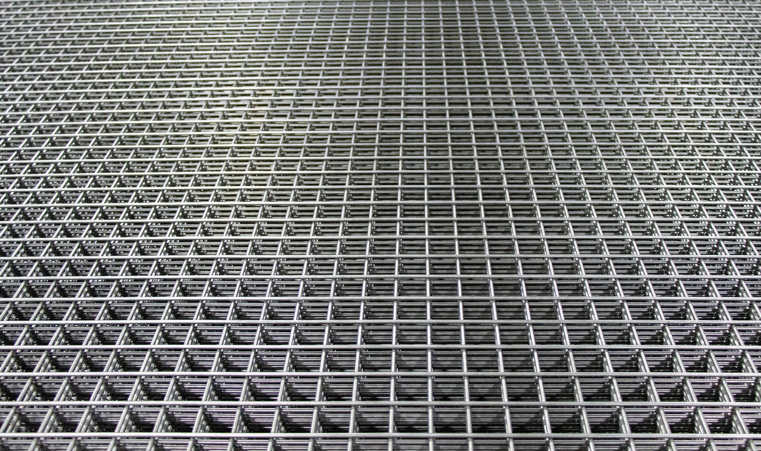
    Welded reinforcing mesh (also called fabric reinforcement or wire mesh) is a factory-produced grid of longitudinal and transverse wires or bars welded at each intersection. Panels are manufactured to standard dimensions — a common European panel size is 6.0 × 2.3 m — or cut to bespoke sizes. The welded intersections are formed by electrical resistance welding, producing a joint with defined strength.

    In Germany and Europe, mesh is classified under DIN 488-4 (part of the DIN 488 standard family) and is typically produced from B500A wire (normal ductility, cold-rolled from coil) for standard Q/R types. The material conforms to EN 10080.

    What Are Loose Bars?

    Loose bars are individual straight reinforcing bars — typically B500B (hot-rolled, high ductility) in diameters from 8 to 40 mm, supplied in stock lengths of 6–18 m (most commonly 12 m). For slab work, bars are cut to required lengths on site or as factory cut-and-bend supply, then placed and tied (or clipped) by hand to form the required two-way grid.

    Head-to-Head Comparison

    FactorWelded MeshLoose Bars
    Typical gradeB500A (normal ductility)B500B (high ductility)
    Fixing speed on siteFast — panels lifted and positionedSlower — individual bars placed and tied
    Geometric flexibilityLimited — standard panel sizes; offcuts as wasteHigh — any diameter, spacing, or shape
    WasteOffcuts at edges and irregular shapesLow if cut-and-bend supply used
    Structural ductilityB500A: Agt ≥ 2.5%, k ≥ 1.05B500B: Agt ≥ 5.0%, k ≥ 1.08
    Seismic suitabilityGenerally not for DCM/DCH seismic designB500B (or B500C) suitable per Eurocode 8
    LogisticsLarge, flat panels — efficient for regular slabsBundles of bars — flexible in tight spaces
    Cost (material)Generally competitive for regular slabsVaries with diameter and quantity
    DocumentationEN 10204 3.1 MTC per mesh typeEN 10204 3.1 MTC per bar grade/heat

    When to Choose Welded Mesh

    Welded mesh is typically the preferred option for:

    • Ground-bearing slabs on grade — regular geometry, high coverage area, where speed of placement is critical.
    • Industrial floor slabs — large, repetitive areas with standard reinforcement density.
    • Suspended slabs with regular bay sizes — where standard mesh panel dimensions align well with slab geometry.
    • Projects where labour cost is high — the speed advantage of mesh panels can reduce fixing time and overall programme significantly.

    When to Choose Loose Bars

    Loose bars (particularly factory cut-and-bend B500B) are generally preferred for:

    • Irregularly shaped slabs — curved edges, penetrations, or complex geometry that would produce excessive mesh waste.
    • Heavily reinforced suspended slabs — where high ductility (B500B/B500C) is required by the structural design or seismic specification.
    • Thick slabs with large bar diameters — mesh is generally limited to smaller wire sizes; heavy reinforcement requires individual bars.
    • Seismically designed structures — Eurocode 8 requires Class B or C ductility (B500B or B500C) for primary seismic elements; standard mesh (B500A) is often insufficient.

    Combined Approaches

    Many projects use both: standard mesh panels in the main body of a slab, with loose bar trimmings and additional bars at openings, edges, column heads, and where extra reinforcement is required. This hybrid approach can optimise both speed and flexibility.

    For detailed mesh specifications see our reinforcing steel mesh page. For loose B500B bars see our B500B rebar product page. Both options are available with full EN 10204 3.1 Mill Test Certificates and export documentation.

    Frequently Asked Questions

    Common questions about welded mesh versus loose bars for slab reinforcement.

    Is welded mesh the same as loose bar reinforcement in terms of structural performance?
    Not exactly. Standard European mesh is produced from B500A wire (normal ductility, Agt ≥ 2.5%), while loose bars are typically B500B (high ductility, Agt ≥ 5.0%). For most slab applications this is not limiting, but seismic design codes (Eurocode 8) require Class B or C ductility in primary seismic elements, which standard mesh may not satisfy. Always confirm the grade requirement with the structural engineer.
    What is the standard mesh panel size in Germany?
    A common panel size in the German/European market is 6.0 × 2.3 m, but other sizes are available. Standard mesh types (Q and R series in DIN 488-4) cover a range of wire diameters and spacings. Bespoke cut-to-size panels can also be manufactured for specific project requirements.
    Can welded mesh be used for suspended (elevated) slabs?
    Yes, welded mesh is widely used in suspended slabs. For simple one-way or two-way spanning slabs with moderate loading, standard mesh may be sufficient. However, heavily loaded slabs, flat slabs with punching shear requirements, and seismically designed structures typically require loose bars (B500B) or supplementary bars in addition to mesh.
    How do I calculate the weight of a welded mesh panel for a tonnage estimate?
    Multiply the wire cross-sectional area by density (7850 kg/m³) and total wire length in the panel, or use the standard formula: kg/m = d² × 0.00617 for individual wires. For a full mesh panel, manufacturers provide a nominal weight per panel (kg) and weight per m² in their product data sheets.

    Source German-standard rebar with full export documentation

    Tell us your specification and destination port — we’ll respond with a detailed quotation.

    Request a Quote →
  • Reinforcing Steel for Culverts

    Reinforcing Steel for Culverts

    Application Guide

    Reinforcing Steel for Culverts: Bar Sizes, Arrangement, and Supply

    Culverts carry watercourses and drainage channels beneath roads, railways, and embankments. In reinforced concrete form — box sections, arched, or circular barrel — they demand reinforcement detailing that handles soil and traffic loading, hydrostatic pressure, and long service-life durability. Steel Rebar Germany supplies B500B bar, mesh, and cut-and-bend cages to DIN 488 and EN 10080 for culvert construction projects worldwide.

    DIN 488 · EN 10080 Mill Test Certificate Worldwide export

    Culvert Structural Forms and Reinforcement Implications

    Cast-in-place and precast reinforced concrete culverts take three principal forms, each with distinct reinforcement demands:

    • Box culverts (rectangular cross-section): The most common form for road and railway drainage. Four reinforced walls — base slab, two side walls, and a roof slab — each spanning between corners. The corner connections carry moment continuity and require carefully detailed L-bars or bent U-bars. Haunch reinforcement at internal corners redistributes stress concentrations.
    • Arch culverts: A curved barrel acting primarily in compression, with circumferential hoop reinforcement resisting ring tension under unsymmetrical loading. Longitudinal bars provide temperature and crack control.
    • Circular pipe culverts (precast): Short segments joined by spigot-and-socket or steel-ring joints. Reinforcement is typically a single or double cage of circumferential and longitudinal bars.

    For box and arch culverts under significant fill or traffic loading, B500B high-ductility bar (DIN 488 Class B) is the standard specification. For lightly loaded precast pipe sections, B500A may be acceptable subject to the precast manufacturer’s design.

    Typical Bar Sizes and Arrangement

    The following indicative values apply to in-situ reinforced concrete box culverts under moderate road loading. Heavier loading (HA/HB, SLW60/SLW30 per DIN 1072), deep fill, or waterway scour will require larger bars and closer spacing.

    Culvert ElementTypical Bar DiaTypical SpacingWeight kg/m
    Roof slab — main span steelØ12–16 mm B500B150–200 mm0.888–1.58 kg/m
    Roof slab — distribution steelØ10–12 mm B500B200–250 mm0.617–0.888 kg/m
    Base slab — main steelØ12–16 mm B500B150–200 mm0.888–1.58 kg/m
    Side walls — vertical barsØ10–12 mm B500B150–200 mm0.617–0.888 kg/m
    Side walls — horizontal barsØ8–10 mm B500B200–300 mm0.395–0.617 kg/m
    Haunch / corner L-barsØ12–16 mm B500B150–200 mm0.888–1.58 kg/m
    Indicative figures only. Bar sizes and spacing must be confirmed by a qualified structural engineer to project-specific loading, fill depth, hydrological conditions, and applicable national standards.

    Concrete Cover for Culverts

    Culverts are in contact with soil, water, and in some cases chemically aggressive ground conditions. Appropriate exposure classes and nominal cover are:

    • Soil-buried faces (XC2 / XC4): cnom ≥ 35–40 mm depending on water table and soil chemistry.
    • Waterway-exposed soffit (XD1 / XF1): cnom ≥ 40–45 mm; freeze-thaw class XF1 applies in temperate climates.
    • Aggressive ground / sulphate-bearing soils (XA1–XA3): additional concrete mix requirements (sulphate-resisting cement, low w/c ratio); cover as for XC4 as a minimum.

    Spacers at maximum 800 mm centres ensure correct cover on both faces and at the base mat.

    Corner and Haunch Detailing

    The internal corners of box culverts are stress concentration points. Eurocode 2 requires that the reinforcement at re-entrant corners is carefully detailed to avoid cracking due to the indirect tension that develops. Common solutions include:

    • Diagonal bars: additional Ø10–12 mm B500B bars placed diagonally across the internal corner at 45°, typically two layers.
    • Haunches: a triangular concrete fillet at each internal corner, reinforced with hairpin or L-shaped bars, reduces the effective span and smooths the stress flow.
    • Bent U-bars: continuous U-shaped bars at corners carry the moment continuity between the slab and wall without a lap joint at the corner.

    Supply Options and Prefabrication

    For large culvert programmes, Steel Rebar Germany can supply complete cut-and-bend reinforcement packages:

    • Cut-and-bend bar schedules: all bars cut to length and bent to DIN 488 or BS 8666 shape codes, delivered in labelled bundles matched to the bar bending schedule. Dramatically reduces site waste and fabrication time.
    • Straight B500B bar stock: dia 8–32 mm in 6–18 m lengths for site cutting where the geometry varies across culvert bays.
    • Welded mesh panels (B500A): suitable for flat slab components of box culverts as main or distribution reinforcement.

    See also our infrastructure and bridges page and cut-and-bend service for related application and supply guidance.

    Frequently Asked Questions

    Common questions about reinforcing steel for culvert structures.

    What rebar grade is used for reinforced concrete culverts?
    B500B (DIN 488 / EN 10080 Class B, high ductility) is the standard grade for in-situ reinforced concrete culverts. Its 500 MPa yield strength, k ≥ 1.08, and Agt ≥ 5.0 % suit the combined bending, shear, and hoop tension loading of culvert structures. B500A welded mesh may be used for distribution reinforcement in flat slab components subject to design approval.
    How do you reinforce the corners of a box culvert?
    Internal corners are reinforced with diagonal bars (typically Ø10–12 mm at 45°), bent U-bars providing moment continuity, or haunches with hairpin bars. The method depends on the corner geometry and moment demand. Eurocode 2 Clause 8.7 provides guidance on reinforcement at corners, and the structural engineer will detail the required arrangement based on the design forces.
    What concrete cover is needed for a culvert invert?
    The invert (base slab soffit) is in contact with running water and potentially chemically active sediment. Exposure class XC4 (cyclic wet/dry) is a minimum; XA1–XA3 applies where aggressive groundwater is present. Nominal cover is typically cnom ≥ 40 mm for XC4, increasing to 50 mm or more for aggressive chemical environments. The structural engineer specifies cover based on site-specific ground investigation results.
    Can you supply a complete bar bending schedule for a culvert?
    We can supply against your existing bar bending schedule (BBS), producing cut-and-bend material to DIN 488 or BS 8666 shape codes. If your project team needs support with the BBS itself, this must be produced by the project’s structural engineer — we supply the fabricated steel to the schedule provided. Contact us via the quote form with your schedule and project details.
    Is culvert reinforcement suitable for container export?
    Yes. Straight bar bundles (up to 18 m lengths) are consolidated in open-top or flat-rack containers, or break-bulk where needed. Cut-and-bend culvert cages, sorted by element and schedule reference, fit into standard 40 ft containers. Each bundle carries a heat-traceable label matched to the EN 10204 3.1 Mill Test Certificate. Contact us for freight and container options to your destination port.

    Source German-standard rebar with full export documentation

    Tell us your specification and destination port — we’ll respond with a detailed quotation.

    Request a Quote →
  • Reinforcing Steel for Parapets

    Reinforcing Steel for Parapets

    Application Guide

    Reinforcing Steel for Parapets: Detailing, Cover, and Supply

    Parapets are exposed cantilever walls at the edge of roofs, bridges, and elevated platforms. Their reinforcement must resist horizontal wind and barrier loading while enduring some of the harshest durability conditions of any structural element. Steel Rebar Germany supplies B500B bar, cut-and-bend cages, and mesh to DIN 488 and EN 10080 for parapet construction worldwide.

    DIN 488 · EN 10080 Mill Test Certificate Worldwide export

    Why Parapet Reinforcement Is a Specialist Topic

    Compared with most reinforced concrete walls, parapets present two compounding challenges. First, they are cantilevers — the critical bending moment is at the base, where the parapet connects to the slab or beam below, making the starter-bar connection and the anchorage length into the supporting structure the most important reinforcement detail. Second, they are fully exposed on both faces to wind-driven rain, freeze-thaw cycles, de-icing salts (on bridges and car parks), and UV radiation — meaning durability and concrete cover must be designed conservatively.

    Eurocode 2 (EN 1992-1-1) classifies exposed bridge parapets and barrier systems in exposure class XD3 or XS3 (chloride-rich environments), while building parapets typically fall under XC3/XC4 with XF1 freeze-thaw in northern climates.

    Typical Bar Sizes and Arrangement

    Parapet reinforcement typically consists of vertical bars (resisting the cantilever bending moment at the base) and horizontal bars (providing minimum crack control reinforcement and acting as distribution steel). Indicative values are given below — always design to project-specific loading and national annex.

    Parapet HeightVertical Bars (face)Horizontal BarsIndicative Spacing
    Up to 600 mmØ10 mm B500BØ8 mm B500BVert @ 200 mm; Horiz @ 300 mm
    600 – 1 000 mmØ12 mm B500BØ8 mm B500BVert @ 150–200 mm; Horiz @ 250–300 mm
    1 000 – 1 500 mm (bridge barrier)Ø16 mm B500BØ10 mm B500BVert @ 125–150 mm; Horiz @ 200–250 mm
    High-load or crash barrier2 × Ø16 or Ø20 mm B500BØ10–12 mm B500BPer engineer; crash-test certified design
    Indicative figures only. Parapet loading (wind pressure, barrier impact, vehicular restraint) varies widely. All bar sizing and spacing must be confirmed by a qualified structural engineer.

    Concrete Cover for Parapets

    Cover requirements for exposed parapets are among the most demanding in building and civil construction:

    • Building parapets (XC4 / XF1): cnom ≥ 40 mm typically required; cnom = 45 mm recommended with Δcdev = 10 mm.
    • Bridge parapets (XD3): EN 1992-2 specifies cmin,dur = 45 mm for XD3 with C35/45 concrete → cnom ≈ 55 mm.
    • Marine / coastal parapets (XS3): cmin,dur = 45 mm minimum; additional durability measures (stainless steel or epoxy-coated rebar, low w/c ratio, silica fume concrete) are common design responses.

    Robust spacers at maximum 750 mm centres on both faces are essential to maintain cover on thin parapet walls. Steel Rebar Germany can supply DBV-compliant spacers alongside the bar order.

    Starter Bar Anchorage at the Base

    The connection between the parapet vertical bars and the parent slab or beam is the structural hinge of the detail. The anchorage length lbd into the supporting member must be sufficient to transfer the full design tensile force. For Ø12 B500B bars in C30/37 concrete, indicative basic anchorage lengths are approximately 500–600 mm depending on bar position, bond conditions, and any transverse pressure — confirm with EN 1992-1-1 Clause 8.4.

    On bridge and highway parapets, starter-bar couplers (parallel-thread mechanical splices) are increasingly used to allow top-slab construction before parapet erection, avoiding protruding bars during the deck pour. Steel Rebar Germany supplies rebar couplers in dia 12–40 mm compatible with B500B bar.

    Supply Options

    Parapet reinforcement is available in several supply configurations:

    • Cut-and-bend prefabricated cages: vertical bars, horizontal bars, and any U-bar or hook details bent to DIN 488 shape codes for immediate placement. Reduces site waste and labour.
    • Straight B500B bar (dia 8–20 mm): for site cutting and bending where the parapet geometry varies along its length.
    • Welded mesh panels (B500A): for flat parapet walls where mesh can be laid as the main reinforcement mat — economical for repetitive uniform sections.
    • Mechanical couplers: for starter-bar splicing at the slab/parapet interface.

    Related Products and Pages

    Parapet reinforcement often intersects with other product and service areas. Buyers may also be interested in our cut-and-bend service for fabricated parapet cages, rebar couplers for mechanical starter-bar connections, and our infrastructure and bridges application page for bridge-specific reinforcement guidance.

    Frequently Asked Questions

    Common questions about reinforcing steel for parapet walls.

    Why is parapet reinforcement more demanding than standard wall reinforcement?
    Parapets are fully exposed cantilevers subject to lateral wind and barrier loads, freeze-thaw cycling, rain penetration from above and the sides, and often chloride exposure in bridge and car park environments. The combined structural (cantilever bending) and durability (high cover, low water-cement ratio) demands make parapet detailing more rigorous than an interior wall of the same dimensions.
    What concrete cover is required for bridge parapets?
    For bridge parapets in exposure class XD3 (chloride environment from de-icing salts), EN 1992-2 typically requires cmin,dur = 45 mm, leading to a nominal cover cnom ≈ 55 mm with the standard 10 mm construction tolerance. Higher covers or supplementary protection (stainless or coated bars, increased concrete grade) are used in severe marine environments (XS3).
    Can rebar couplers be used for parapet starter bars?
    Yes, and they are widely used on bridge decks. Threaded mechanical couplers (parallel-thread or taper-thread type) allow the deck slab to be cast and de-shuttered without protruding vertical bars. The parapet cage is then connected to the coupler sockets at the appropriate construction stage. Steel Rebar Germany supplies couplers compatible with B500B bar in dia 12–40 mm. See the couplers page.
    Is B500B or B500A specified for parapet reinforcement?
    B500B (EN 10080 Class B, high ductility) is the standard grade for structural parapet members that resist lateral loading. B500A welded mesh may be used as secondary distribution reinforcement in the parapet wall face where the primary structure is provided by B500B vertical bars — always per the structural design specification.
    What export documentation is supplied with parapet rebar?
    Each consignment is supplied with EN 10204 3.1 Mill Test Certificates traceable to the heat, a CE Declaration of Performance (DoP) under EN 10080, a Certificate of Origin, and a detailed packing list identifying grade, diameter, heat number, and bundle reference. Full export documentation is standard. Visit our export and delivery page for more detail.

    Source German-standard rebar with full export documentation

    Tell us your specification and destination port — we’ll respond with a detailed quotation.

    Request a Quote →
  • Reinforcing Steel for Lintels

    Reinforcing Steel for Lintels

    Application Guide

    Reinforcing Steel for Lintels: Bar Sizes, Arrangement, and Supply

    Lintels span openings in masonry and concrete walls, transferring load around doors, windows, and service penetrations. Correct reinforcement detailing — bar diameter, arrangement, concrete cover, and end anchorage — is essential for structural performance and durability. Steel Rebar Germany supplies B500B bar, mesh, and cut-and-bend lintel reinforcement to DIN 488 and EN 10080.

    DIN 488 · EN 10080 Mill Test Certificate Worldwide export

    Structural Role of a Lintel

    A lintel is essentially a short-span beam. It picks up the load of the wall (and any floor or roof loads distributed to it) above an opening and transfers that load to the supporting masonry or concrete on each side. Depending on the opening width, wall thickness, and superimposed load, a lintel can be a simple in-situ concrete beam, a precast unit, or a composite masonry-beam system.

    In all cases the tensile reinforcement at the soffit, the shear links, and the anchorage at each bearing are the critical details. Under Eurocode 2 (EN 1992-1-1), lintels follow the same flexural and shear design principles as beams.

    Typical Bar Sizes and Arrangement

    Bar sizing depends on span, loading, and beam depth. The indicative figures below are typical for residential and light-commercial lintels — always design to project-specific calculations.

    Opening WidthTypical Tension BarTypical Shear LinkIndicative Bar Weight
    Up to 900 mm2 × Ø10 mm B500BØ6 @ 150 mm≈ 0.617 kg/m per bar
    900 – 1 500 mm2 × Ø12 mm B500BØ6 @ 150 mm≈ 0.888 kg/m per bar
    1 500 – 2 400 mm3 × Ø12 or 2 × Ø16 mm B500BØ8 @ 150 mm≈ 1.58 kg/m per Ø16 bar
    2 400 – 3 600 mm3 × Ø16 or 2 × Ø20 mm B500BØ8 @ 125 mm≈ 2.47 kg/m per Ø20 bar
    Over 3 600 mmEngineer-designed — typically 2–4 × Ø20–25 mmØ10 @ 100–125 mm≈ 3.85 kg/m per Ø25 bar
    Indicative figures only. Bar quantities and spacing must be verified by a qualified structural engineer against actual loading, concrete grade, and national annex requirements.

    Concrete Cover Requirements

    Concrete cover protects reinforcement from corrosion and provides fire resistance. For lintels, the nominal cover cnom is the sum of the minimum cover cmin and the construction tolerance Δcdev (typically 10 mm under EN 1992-1-1):

    • Internal conditions (XC1): cmin,dur = 15 mm → cnom ≈ 25 mm
    • External sheltered (XC3/XC4): cmin,dur = 25 mm → cnom ≈ 35 mm
    • Exposed / near-coastal (XS1, XD1): cmin,dur ≥ 35 mm → cnom ≈ 45 mm

    Spacers and chairs to DBV standard are available through Steel Rebar Germany to maintain correct cover at the soffit and sides of the lintel form.

    End Anchorage and Bearing Length

    The tension bars at the soffit must be anchored beyond the support centreline. EN 1992-1-1 requires that at simple end supports, at least 25 % of the mid-span tensile reinforcement is carried to the support and anchored with a basic anchorage length lbd. In practice, for lintels in masonry:

    • A minimum bearing length of 150 mm on each side is commonly adopted.
    • Standard 90° hooks or U-bars at each end achieve anchorage in compact lintel depths.
    • For precast lintel systems, the manufacturer’s engineered anchorage details supersede general guidance.

    Supply Options from Steel Rebar Germany

    Lintel reinforcement can be supplied in several forms depending on project size and site capability:

    • Straight bar stock (B500B, dia 8–40 mm, 6–18 m): cut on site to required lengths. Economical for large projects with capable site fabrication.
    • Cut-and-bend service: bars cut to length and bent to DIN 488 shape codes (equivalent to BS 8666). Ready-to-place cages reduce site labour and waste. Suitable for any project scale.
    • Welded mesh (B500A): for lintels with a wide, shallow beam cross-section where a mesh panel can be used as the reinforcement cage.
    • B500A coil-fed stirrups: shear links produced from B500A coil on automated machines — cost-effective for high quantities of identical link sizes.

    See our cut-and-bend service and B500B bar product pages for full specification details.

    Export Packaging for Lintel Reinforcement

    Cut-and-bend lintel cages and straight bar bundles are packed in seaworthy bundles suitable for container loading. Each bundle is labelled by diameter, heat number, and cut/bend schedule reference. EN 10204 3.1 Mill Test Certificates are issued per heat, with traceability through to the finished bar. Consignments are typically consolidated into 20 ft or 40 ft containers for export, with a full packing list and Certificate of Origin for customs clearance in the destination country.

    Frequently Asked Questions

    Common questions about reinforcing steel for lintel applications.

    What grade of rebar is standard for lintels?
    B500B (DIN 488 / EN 10080 Class B) is the standard structural grade for cast-in-place lintel beams in Germany and across the EU. It provides 500 MPa minimum yield strength with high ductility (Agt ≥ 5.0 %), which is required by Eurocode 2 for primary structural members. B500A mesh may be used for non-structural or lightly loaded configurations where Class A ductility is accepted by the design.
    How is the correct bar diameter for a lintel determined?
    Bar diameter is determined by structural calculation based on the bending moment at mid-span (a function of the opening width, lintel depth, and superimposed load), the required moment capacity, and the arrangement of reinforcement within the section. The indicative sizes in this guide are typical starting points; final specification must be confirmed by a qualified structural engineer.
    Can you supply pre-bent lintel cages ready to place?
    Yes. Steel Rebar Germany offers a cut-and-bend service producing lintel cages (tension bars, compression bars if required, and shear links) to DIN 488 shape codes. Provide your bar bending schedule or structural drawings and we can produce export-ready cages. See the cut-and-bend page for details.
    What is the minimum bearing length for a lintel on masonry?
    A bearing length of 150 mm on each side is a widely used practical minimum for lintels on masonry piers in residential construction. The structural engineer may specify a greater bearing depending on bearing stress, masonry strength, and load. Anchorage requirements for the reinforcement bars are calculated per EN 1992-1-1 independently of the bearing length.
    Do you supply spacers and chairs to maintain cover in lintels?
    Yes. Plastic and mortar spacers complying with DBV guidelines are available as accessories. The correct spacer thickness is determined by the specified nominal cover. Spacers should be placed at regular intervals (typically ≤ 1 000 mm) along the soffit and sides of the lintel form to maintain cover throughout concreting.

    Source German-standard rebar with full export documentation

    Tell us your specification and destination port — we’ll respond with a detailed quotation.

    Request a Quote →
  • What Size Rebar for A bridge deck?

    What Size Rebar for A bridge deck?

    Bridge Engineering Rebar Guide

    What Size Rebar for a Bridge Deck?

    Practical bar-size and spacing guidance for reinforced concrete bridge decks — B500B diameters, top and bottom mat layouts, cover depths and indicative steel estimates to DIN 488 / EN 10080.

    DIN 488 · EN 10080 Mill Test Certificate Worldwide export

    What Size Rebar for a Bridge Deck — The Key Diameters

    Bridge decks are among the most demanding reinforced concrete applications. They carry dynamic traffic loads, thermal cycles, de-icing salt exposure and sometimes seismic forces — all demanding high-ductility steel with reliable bond characteristics. B500B rebar in 12 mm to 20 mm diameter forms the structural backbone of most bridge deck designs, with 16 mm being particularly common for primary longitudinal and transverse bars. Shear reinforcement (stirrups, links, U-bars) typically uses 10–12 mm. These are indicative figures — bridge decks are designed to national standards (e.g. EN 1992-2 / Eurocode 2 Part 2 for bridges, or DIN-Fachbericht 102) and every deck requires a formal structural design by a qualified bridge engineer.

    Steel Rebar Germany supplies B500B hot-rolled ribbed bar, welded mesh and cut-and-bend pieces to DIN 488 / EN 10080 for bridge contractors worldwide, complete with EN 10204 3.1 Mill Test Certificates and full export documentation. See our infrastructure and bridges applications page for the broader picture.

    Bridge Deck Reinforcement Layout: Top and Bottom Mats

    A reinforced concrete bridge deck typically uses a two-mat system — a bottom mat carrying positive bending moment (sagging) between supports, and a top mat carrying negative bending moment (hogging) over supports and at cantilever edges. Key characteristics:

    • Bottom mat (positive moment region): Larger bars at closer spacing — typically 16–20 mm at 100–150 mm longitudinally, 12–16 mm at 150–200 mm transversely
    • Top mat (negative moment / hogging zone): Similar or slightly lighter than bottom mat — 14–20 mm at 125–175 mm longitudinally
    • Transverse distribution bars: 12–16 mm at 150–200 mm centres
    • Shear links / stirrups in edge beams and box girder webs: 10–12 mm, spacing governed by shear demand (typically 100–200 mm)
    • Skin reinforcement on deep web faces: 10–12 mm at 150–300 mm

    Typical Bridge Deck Rebar Sizes by Element

    Indicative figures only — bridge span, deck thickness, traffic loading (LM1, LM2 per EN 1991-2), seismic zone, skew angle and applicable bridge standard all govern the final specification. Always rely on the stamped structural design.
    Deck ElementTypical Bar Dia (mm)Typical Spacing (mm)Grade
    Bottom mat — longitudinal (primary)16–20100–150B500B
    Bottom mat — transverse12–16150–200B500B
    Top mat — longitudinal (hogging)14–20100–175B500B
    Top mat — transverse12–16150–200B500B
    Shear links / stirrups10–12100–200B500B
    Edge beam / parapet bar12–20100–150B500B
    Skin reinforcement (webs)10–12150–300B500B

    Bar Weight Reference — Bridge Deck Diameters

    Weight formula: kg/m = d²(mm) × 0.00617. Key sizes for bridge deck work:

    Diameter (mm)Weight (kg/m)Cross-section (mm²)
    100.61778.5
    120.888113
    161.58201
    202.47314
    253.85491
    326.31804

    A typical highway bridge deck slab (250–300 mm thick, two-mat system) may contain 120–200 kg/m³ of reinforcement. For a deck 15 m wide and 50 m long at 160 kg/m³ and 275 mm thick, indicative steel content is approximately 33 tonnes. These are indicative figures for budgeting only; the bar schedule from the approved bridge design is the definitive source.

    Cover Depths and Durability for Bridge Decks

    Bridge decks are exposed to harsh environments — often XD3 (frequently wet, chloride from road salts) or XS1–XS3 (marine). Minimum concrete cover per EN 1992-1-1 / EN 1992-2 for bridge decks:

    • Top (trafficked) surface with waterproofing membrane: nominally 45–60 mm cover under the membrane, though the membrane provides additional protection
    • Top (trafficked) without membrane, exposed to de-icing salts (XD3): minimum cnom 50–60 mm
    • Bottom face / soffit (XC3–XC4 exposure): minimum cnom 35–45 mm
    • A Δcdev allowance of +10 mm is typically added to the minimum for structural design

    DBV-certified plastic bar chairs and spacers are used to hold both mats at correct depth; see our rebar spacers and accessories range. For construction joints, mechanical rebar couplers (12–40 mm) eliminate the congestion of lapping large bars.

    Supply Formats for Bridge Deck Reinforcement

    Bridge contracts specify tightly controlled bar dimensions and traceability. Steel Rebar Germany supplies:

    • B500B hot-rolled ribbed bar, 8–40 mm, in 6–12 m stock lengths — heat-traceable to EN 10204 3.1 MTCs
    • Cut-and-bend to DIN 488 or BS 8666 shape codes — pre-tagged bar bundles matching the bar schedule, reducing on-site labour
    • Mechanical couplers (parallel-thread, 12–40 mm) for construction joint splices
    • Welded mesh (DIN 488-4) for lightweight deck overlays or secondary reinforcement zones

    All shipments are seaworthy-bundled (~2 t lifts) for container or break-bulk export. Full documentation: EN 10204 3.1 MTC, Certificate of Origin, CE/DoP, packing lists. See also our related guides: rebar for box culverts and rebar for concrete roads.

    Frequently Asked Questions

    Common questions on rebar sizing for concrete bridge decks

    What is the typical rebar diameter for a concrete bridge deck?
    Most highway bridge decks use 16 mm B500B as the primary bar for both top and bottom longitudinal mats, with 12–16 mm transverse bars. Heavily loaded or long-span decks may use 20–25 mm for the primary longitudinal steel. Shear links are typically 10–12 mm. The exact size depends on span, loading and deck thickness — always rely on the stamped structural design by a bridge engineer.
    Why is B500B used rather than B500A for bridge decks?
    B500B (Agt ≥ 5.0%, k ≥ 1.08) provides the high ductility and strain-hardening capacity required for structures subject to dynamic traffic loading and potential seismic or impact events. B500A (Agt ≥ 2.5%) is permitted only for specific non-structural applications in bridges — the primary structural reinforcement must meet the B500B ductility class. EN 1992-2 and most national bridge codes mandate B or C ductility class for deck reinforcement.
    What concrete cover is required over rebar in a bridge deck?
    For bridge decks exposed to de-icing salts (exposure class XD3), nominal cover is typically 50–60 mm on the top face and 35–50 mm on the soffit. Where a waterproofing membrane covers the deck, reduced nominal cover (45–50 mm) is sometimes permitted under the membrane. The designer applies a Δcdev tolerance allowance on top of the minimum, typically +10 mm. Always follow the cover specified in the bridge design drawings.
    How much rebar does a bridge deck typically require per square metre?
    A reinforced concrete bridge deck slab (250–300 mm thick, two-mat system, highway loading) typically contains 120–200 kg/m³ of concrete, equivalent to approximately 30–60 kg/m² of deck surface area. Heavily loaded or cantilever deck overhangs may exceed this. These are indicative figures — the bar bending schedule from the structural drawing is the only accurate source for project quantities.
    Does Steel Rebar Germany supply rebar for bridge projects with full traceability documentation?
    Yes. All B500B bar we supply carries EN 10204 3.1 Mill Test Certificates traceable to heat and cast number, meeting the traceability requirements of EN 1992-2 and most national bridge specifications. We also provide Certificate of Origin, CE Declaration of Performance (DoP) and full packing lists. Cut-and-bend pieces are tagged to your bar schedule reference numbers on request.

    Source German-standard rebar with full export documentation

    Tell us your specification and destination port — we’ll respond with a detailed quotation.

    Request a Quote →
  • What Size Rebar for A concrete road?

    What Size Rebar for A concrete road?

    Road Pavement Rebar Guide

    What Size Rebar for a Concrete Road?

    Practical bar-size and spacing guidance for reinforced concrete road pavements — B500B diameters, mat layout, cover depths and indicative steel estimates to DIN 488 / EN 10080.

    DIN 488 · EN 10080 Mill Test Certificate Worldwide export

    What Size Rebar for a Concrete Road — The Key Numbers

    Concrete road pavements are one of the largest consumers of flat reinforcing steel in civil engineering. The primary function of the rebar is crack control and load transfer, not pure flexural capacity — concrete roads flex very little but can crack from thermal movement, shrinkage and differential settlement. B500B rebar in 10 mm to 16 mm diameter, placed in a two-way mat at 150–200 mm centres, is the dominant specification for continuously reinforced concrete pavement (CRCP) and jointed reinforced concrete pavement (JRCP). Mesh (DIN 488-4) is widely used for lighter-duty or local roads. These are indicative figures — the exact specification must be determined by a pavement design engineer to the applicable standard (e.g. EN 1992-1-1, RStO, or the national road authority specification).

    Steel Rebar Germany supplies B500B bar, reinforcing mesh and cut-and-bend pieces to DIN 488 / EN 10080 for road contractors worldwide, with EN 10204 3.1 Mill Test Certificates and full export documentation.

    Concrete Road Types and Reinforcement Strategy

    Three main concrete pavement types influence rebar choice:

    • Continuously Reinforced Concrete Pavement (CRCP): No transverse contraction joints; reinforcement (longitudinal steel, typically 0.6–0.7% of the cross-section) holds crack widths tight. Typical longitudinal bars: 12–16 mm B500B at 150 mm; transverse: 10–12 mm at 300–600 mm.
    • Jointed Reinforced Concrete Pavement (JRCP): Transverse joints at 12–30 m spacing; reinforcement controls cracking between joints. Typical mesh or bar mat: 10–12 mm at 150–200 mm two-way.
    • Dowel Bar Assemblies: Round bars (plain or epoxy-coated) at transverse joints for load transfer — not structural reinforcement per se but often part of the rebar supply package. Diameters typically 20–32 mm (to specific road authority standards).

    Typical Rebar Sizes for Concrete Road Pavement

    Indicative figures only — pavement thickness, subgrade CBR, traffic loading class (e.g. AASHTO, German RStO), climate zone and applicable standard will all determine the final specification. Always obtain a formal pavement design.
    Application / Pavement TypeTypical Bar Dia (mm)Typical Spacing (mm)Placement
    CRCP longitudinal steel12–16125–175Mid-depth or upper third
    CRCP transverse steel10–12300–600Mid-depth
    JRCP two-way mat10–12150–200Mid-depth
    Industrial / port pavement (heavy)16–20125–150Bottom and/or top mat
    Local road / residential8–10 (mesh)150–200Mid-depth
    Dowel bars (joint load transfer)20–32300–450At transverse joints

    Bar Weight Reference

    Formula: kg/m = d²(mm) × 0.00617. Sizes most relevant to road pavement:

    Diameter (mm)Weight (kg/m)Cross-section (mm²)
    100.61778.5
    120.888113
    161.58201
    202.47314

    For a CRCP lane (3.75 m wide, 200 mm thick, 1 km length) using 12 mm longitudinal at 150 mm and 10 mm transverse at 400 mm, indicative steel content is approximately 8–12 kg/m² of pavement surface, or roughly 30–45 tonnes per lane-kilometre. These are indicative figures for budgeting only; the detailed bar schedule from the pavement design is the definitive source.

    Cover Depths for Road Pavement Reinforcement

    Cover to reinforcement in concrete road pavements is specified by the pavement standard and exposure class. Typical values:

    • Top face (trafficked surface, exposed to de-icing salts): minimum 45–60 mm (exposure XD3 / XF4)
    • Bottom face (subbase): minimum 35–50 mm (exposure XC3–XC4)
    • For CRCP, bars are typically placed at the mid-depth of the slab or slightly above, controlled by certified plastic bar chairs

    We supply DBV-approved plastic spacers and bar chairs for pavement use — see our rebar spacers and accessories page. For related infrastructure reinforcement, see our guides on rebar for box culverts and rebar for bridge decks.

    Supply Formats for Road Project Rebar

    Road projects typically consume large tonnages of consistently sized bar. We supply:

    • Straight bar (B500B, 8–40 mm, 6–12 m stock lengths) in project-quantity bundles
    • Welded reinforcing mesh (DIN 488-4, Q/R types, standard and custom panels) — preferred for local and secondary roads
    • Cut-and-bend to DIN 488 or BS 8666 shape codes for pre-formed assemblies
    • Rebar coils (6–16 mm B500A/B500B) for automated dowel and stirrup production

    All shipments carry EN 10204 3.1 MTCs and are seaworthy-bundled for container or break-bulk export worldwide.

    Frequently Asked Questions

    Common questions on rebar sizing for concrete road pavements

    What is the typical rebar size for a concrete road pavement?
    For continuously reinforced concrete pavement (CRCP) on highways, 12–16 mm B500B longitudinal bars at 125–175 mm spacing are typical. Transverse steel is lighter at 10–12 mm, 300–600 mm spacing. Local roads and residential pavements often use 8–10 mm welded mesh (Q-type, DIN 488-4) at 150–200 mm. Exact sizing depends on traffic loading class, pavement thickness and climate. Always get a formal pavement design.
    Is reinforcing mesh or individual bar better for concrete road construction?
    Welded mesh (DIN 488-4) is faster to place and suits lighter-duty and local roads where a two-way grid is needed at standard spacing. Individual bars (CRCP style) allow the structural engineer to optimise longitudinal steel content for traffic-specific requirements. For large highway projects, individual bar provides more flexibility. We supply both in the sizes and formats required.
    How do I calculate how much rebar I need for a concrete road?
    Estimate the steel area per metre of pavement width, then convert to kg/m using the weight formula (kg/m = d² × 0.00617). Multiply by total lane length. For CRCP, longitudinal steel area is typically 0.5–0.7% of the concrete cross-section. For example, a 200 mm slab reinforced at 0.6% has 1200 mm² of steel per metre width — achievable with 12 mm bars at 94 mm spacing or 16 mm at 168 mm. Add transverse steel and apply a waste factor. These are indicative calculations — use the pavement design schedule for project quantities.
    Does Steel Rebar Germany supply dowel bars for road construction joints?
    Yes. We supply plain round bars in the diameter ranges used for dowel assemblies (typically 20–32 mm) and can supply to national road authority specifications. Dowel bars for transverse joints are available as plain round bar (cut to length) or as pre-assembled cage units. Contact us with your diameter, length and quantity requirements.
    Can I order rebar for road construction in large project quantities for export?
    Yes. We supply project-scale tonnages of B500B bar, welded mesh and cut-and-bend assemblies for road construction projects worldwide. Shipment is in seaworthy bundles (~2 t lifts) by container or break-bulk. Documentation includes EN 10204 3.1 Mill Test Certificates, Certificate of Origin, CE Declaration of Performance and full packing lists. Use the quote form to share your project specification and destination port.

    Source German-standard rebar with full export documentation

    Tell us your specification and destination port — we’ll respond with a detailed quotation.

    Request a Quote →
  • What Size Rebar for A box culvert?

    What Size Rebar for A box culvert?

    Infrastructure Rebar Guide

    What Size Rebar for a Box Culvert?

    Practical bar-size and spacing guidance for reinforced concrete box culverts — B500B diameters, cover requirements, mat layout and indicative steel estimates to DIN 488 / EN 10080.

    DIN 488 · EN 10080 Mill Test Certificate Worldwide export

    What Size Rebar for a Box Culvert — Key Sizes at a Glance

    Box culverts are buried reinforced concrete structures used to convey drainage, irrigation or traffic under roads and embankments. They carry combined earth, water and live loads, which places serious demands on the reinforcement. B500B rebar in 12 mm to 20 mm diameter is the most common range for main structural bars in culvert walls, base slabs and roof slabs. Distribution and secondary bars are typically 10–12 mm; stirrups and ties 8–10 mm. Spacing is commonly 150–200 mm centres. These are indicative figures — the exact specification must come from a licensed structural engineer using project-specific load analysis to Eurocode 2 / EN 1992-1-1 or the applicable national standard.

    Steel Rebar Germany supplies B500B hot-rolled ribbed bar, welded mesh and cut-and-bend pieces to DIN 488 / EN 10080 standards with full export documentation including EN 10204 3.1 Mill Test Certificates.

    Why B500B Is the Grade of Choice for Culvert Structures

    B500B achieves a minimum yield strength of 500 MPa with a characteristic strain at maximum force Agt ≥ 5.0% and k ≥ 1.08. This high-ductility profile is essential in culvert barrel sections where seismic or dynamic traffic loading could cause plastic hinging — the structure must redistribute forces without brittle failure. The ribbed bar profile ensures strong mechanical bond to the surrounding concrete, critical in thin-wall precast culvert units where cover depths are already near minimum. See our B500B rebar page for available diameters and stock lengths.

    For long culverts and precast elements, cut-and-bend fabrication to DIN 488 shape codes reduces on-site labour and ensures dimensional consistency across repeated cage units. Mechanical rebar couplers (parallel-thread, 12–40 mm) can replace lap splices at construction joints to simplify assembly.

    Typical Rebar Sizes by Culvert Element

    Indicative figures only — culvert span, fill height, highway live loading class, groundwater conditions and applicable code will all affect final bar sizes. Always verify with a qualified structural engineer.
    Culvert ElementTypical Bar Dia (mm)Typical Spacing (mm)Grade
    Base slab — main longitudinal bars16–20125–150B500B
    Base slab — transverse distribution12–16150–200B500B
    Walls — inner face (tension)14–20125–150B500B
    Walls — outer face (compression)12–16150–200B500B
    Roof slab — main bars14–20125–150B500B
    Roof slab — distribution bars10–12150–200B500B
    Stirrups / shear links8–10100–200B500B

    Bar Weight Reference — Key Diameters

    Weight formula: kg/m = d²(mm) × 0.00617. Key sizes for culvert reinforcement:

    Diameter (mm)Weight (kg/m)Cross-section (mm²)
    100.61778.5
    120.888113
    161.58201
    202.47314
    253.85491

    For a single-cell box culvert with internal dimensions 2.0 m × 2.0 m and a 10 m barrel length, indicative rebar content may range from 80–150 kg/m³ of concrete for lightly loaded culverts up to 180–250 kg/m³ for heavily loaded highway culverts under significant fill. A 10 m culvert section might consume approximately 3–8 tonnes of reinforcement. These are indicative figures for budgeting only; the bar-bending schedule derived from the structural drawing is the only accurate source.

    Concrete Cover and Exposure Class Guidance

    Box culverts are classified under EN 1992-1-1 exposure classes that drive minimum cover. Typical classifications for culverts:

    • XC2–XC4: elements permanently or cyclically wet (base slab soffit, inner walls) — cover typically 35–50 mm
    • XD2–XD3: exposure to chlorides from de-icing salts (road drainage culverts) — cover typically 40–55 mm
    • XF2–XF4: freeze/thaw with or without de-icing agents — may increase minimum cover
    • XA1–XA2: chemically aggressive soils or groundwater — cover increase and cement type review required

    Use DBV-certified plastic or concrete spacers to maintain cover during casting; see our rebar spacers and accessories range for suitable products.

    Supply Options for Box Culvert Rebar

    Steel Rebar Germany can supply culvert reinforcement in multiple formats:

    • Straight bar (B500B, 8–40 mm, stock lengths 6–12 m) for contractor-bending on site or in local fab yards
    • Cut-and-bend to DIN 488 or BS 8666 shape codes — supplied as tagged bundles ready for cage assembly
    • Welded reinforcing mesh (DIN 488-4, Q and R types, standard or bespoke panel sizes) for slab elements
    • Rebar coils (6–16 mm B500A/B500B) for automated stirrup and link production
    • Mechanical couplers (12–40 mm) for construction-joint continuity

    All product ships with EN 10204 3.1 Mill Test Certificates and export documentation. See also our guide to rebar sizing for concrete roads — another key infrastructure application.

    Frequently Asked Questions

    Common questions on rebar sizing for box culvert construction

    What rebar diameter is typical for box culvert walls?
    For typical road underpasses and drainage culverts, 14–20 mm B500B is the common range for main wall reinforcement, with 12–16 mm for outer-face (compression) bars. The precise diameter depends on span, fill height and live load — a shallow drainage culvert under a footpath is very different from a multi-lane highway box. Always have a structural engineer specify bar sizes based on the design loads.
    Can precast box culvert segments use the same rebar sizes as cast-in-situ?
    Generally yes, though precast elements are often optimised with slightly higher reinforcement ratios to account for demoulding and handling stresses. Precast factories may use closer bar spacing (100–150 mm) and slightly smaller diameters to improve cage density. We supply both straight bar and cut-and-bend pieces to suit precast yard production schedules.
    How much rebar (kg/m³) does a box culvert typically contain?
    Typical reinforcement intensity ranges from about 80–150 kg/m³ for lightly loaded culverts (low fill, pedestrian loading) to 150–250 kg/m³ or more for heavily loaded highway culverts under deep fill. These are indicative figures — the exact quantity must come from the bar-bending schedule derived from the approved structural design.
    Does Steel Rebar Germany supply rebar in large quantities for infrastructure projects?
    Yes. We supply B500B rebar, welded mesh, cut-and-bend cages and accessories in project quantities for infrastructure contractors worldwide. Shipment is seaworthy-bundled in approximately 2-tonne lifts, suitable for container or break-bulk. Full documentation (EN 10204 3.1 MTC, Certificate of Origin, CE/DoP, packing list) accompanies every shipment. Use the quote form to share your specification and port of delivery.
    Should I use mechanical couplers or lap splices in a box culvert?
    Both are used. Lap splices are standard for lighter bars (up to about 20 mm) where cage geometry allows the overlap length (typically 40–60 × bar diameter for B500B in tension). For larger bars (25–40 mm) or heavily congested construction joints, parallel-thread mechanical couplers eliminate the lap length penalty and reduce concrete placement difficulty. Our coupler range covers 12–40 mm B500B bar.

    Source German-standard rebar with full export documentation

    Tell us your specification and destination port — we’ll respond with a detailed quotation.

    Request a Quote →
  • What Size Rebar for A concrete septic tank?

    What Size Rebar for A concrete septic tank?

    Rebar Sizing Guide

    What Size Rebar for a Concrete Septic Tank?

    Practical bar-size and spacing guidance for reinforced concrete septic tanks — B500B diameters, cover depths, mat layouts and indicative steel estimates — backed by DIN 488 / EN 10080 supply capability.

    DIN 488 · EN 10080 Mill Test Certificate Worldwide export

    What Size Rebar for a Concrete Septic Tank — The Short Answer

    For a typical domestic or light-commercial concrete septic tank, B500B rebar in 10 mm or 12 mm diameter is most commonly specified for walls and slabs, with 8 mm used for secondary distribution bars and stirrups. Spacing of 150–200 mm centres is typical for walls under moderate soil and liquid pressure, while the base slab often calls for 12–16 mm bars at 150 mm centres given combined earth bearing and uplift loads. These are indicative figures — always confirm your design with a licensed structural engineer, as loads vary significantly with tank volume, burial depth, groundwater level and local code requirements.

    Steel Rebar Germany supplies B500B hot-rolled ribbed bar, cut-and-bend pieces and reinforcing mesh to DIN 488 / EN 10080 standards, available for export worldwide with full Mill Test Certificates (EN 10204 3.1) and export documentation.

    Why B500B Is the Standard Choice

    B500B (minimum yield 500 MPa, k ≥ 1.08, Agt ≥ 5.0%) is the dominant reinforcing grade across Germany and the EU under DIN 488 Part 1. Its high-ductility classification makes it suitable for monolithic concrete structures subject to settlement and soil pressure — both of which are relevant in buried septic tank construction. The ribbed surface profile provides excellent bond to concrete, critical in thin-wall tank sections where cover depths can be 40–50 mm to the nearest bar face.

    For septic tank applications, B500A (often used in mesh and coil form) can be appropriate for lightly loaded secondary reinforcement. We supply both grades; see our B500B bar and reinforcing mesh product pages for full size ranges.

    Typical Rebar Sizes and Spacing by Tank Element

    The table below gives indicative bar sizes and spacing for common septic tank elements. These figures are based on general engineering practice for small to medium precast or cast-in-situ tanks; they are starting points for design, not a substitute for a project-specific structural calculation.

    Indicative figures only — tank geometry, soil conditions, groundwater table and applicable national code (e.g. EN 1992-1-1 / Eurocode 2) will all affect the final specification. Always verify with a qualified engineer.
    Tank ElementTypical Bar Dia (mm)Typical Spacing (mm)Grade
    Base slab (main bars)12–16150B500B
    Base slab (distribution bars)10–12150–200B500B
    Walls (horizontal)10–12150–200B500B
    Walls (vertical)10150–200B500B
    Roof / cover slab10–12150–200B500B
    Stirrups / ties8150–200B500B

    Bar Weight Reference — Key Diameters

    Use the formula kg/m = d²(mm) × 0.00617 to estimate weight. Common diameters for septic tank work:

    Diameter (mm)Weight (kg/m)Cross-section (mm²)
    80.39550.3
    100.61778.5
    120.888113
    161.58201

    For a rough estimate of a small tank (e.g. 3 m × 2 m × 2 m internal, walls + base + roof): total reinforced concrete surface area is approximately 40–50 m². At a steel ratio of roughly 10–15 kg/m² for moderate loading, a tank of this size may consume 400–750 kg of rebar. This is an indicative figure for budgeting only — actual quantities depend on the approved engineering drawing.

    Cover Depths and Detailing Notes

    Concrete cover to reinforcement in buried liquid-retaining structures is critical for durability. EN 1992-1-1 / Eurocode 2 and the relevant exposure class (typically XC2–XC4 for buried elements in contact with soil and moisture, or XA1–XA2 for chemically aggressive soils) will determine the minimum cover. Common practice for septic tanks:

    • Minimum cover to outer face (external/soil side): 40–50 mm
    • Minimum cover to inner face (liquid side): 30–40 mm (confirm with corrosion/crack-width requirements)
    • Spacers/chairs: use DBV-certified plastic or concrete spacers; see our rebar spacers and accessories range
    • Lap splice lengths: typically 40–50 × bar diameter for B500B in tension; mechanical couplers (see rebar couplers) can reduce cage congestion

    Ordering Cut-and-Bend or Straight Bar

    For septic tank construction, cut-and-bend service to BS 8666 or DIN 488 shape codes eliminates site labour and reduces waste. Supply options include:

    • Straight stock lengths (6–12 m) for self-bending on site
    • Pre-cut and bent cages or mats to drawing
    • Welded mesh panels (Q/R types, standard or bespoke) for wall and slab reinforcement
    • Rebar coils (6–16 mm B500A/B500B) for automated stirrup bending

    All product is supplied with EN 10204 3.1 Mill Test Certificates, seaworthy bundled for container or break-bulk export.

    Frequently Asked Questions

    Common questions on rebar sizing for concrete septic tanks

    What is the minimum rebar size for a concrete septic tank?
    In most residential applications, 10 mm B500B is the practical minimum for structural elements such as walls and slabs. Some designers use 8 mm for distribution bars or light-duty lids. The actual minimum is set by the structural design, not by a fixed rule — your engineer will determine this based on loads and Eurocode 2 crack-width / deflection checks.
    Can I use reinforcing mesh instead of individual bars for a septic tank?
    Yes. Welded reinforcing mesh (to DIN 488-4) is widely used for tank walls and slabs. Standard Q-type mesh (square grid, 150 mm spacing) in 8–10 mm wire is a common choice for walls of moderate height. Bespoke mesh panels cut to tank dimensions reduce fixing time. We supply standard and custom mesh panels — contact us with your panel sizes and wire diameter.
    What concrete cover is needed over rebar in a buried septic tank?
    Typically 40–50 mm on the external (soil) face and 30–40 mm on the internal (liquid) face, depending on exposure class per EN 1992-1-1. Chemically aggressive soils (XA class) or wastewater with high H₂S may require increased cover or concrete mix adjustments. Always follow the exposure class recommendation from your structural engineer.
    Does Steel Rebar Germany supply rebar to DIN 488 for export?
    Yes. We supply B500B hot-rolled ribbed bar, B500A/B500B coil, welded mesh, cut-and-bend pieces and accessories all to DIN 488 / EN 10080 standards. Export documentation includes EN 10204 3.1 Mill Test Certificates, Certificate of Origin, CE Declaration of Performance, and full packing lists. We can ship container or break-bulk to most global destinations.
    How do I estimate how much rebar a concrete septic tank needs?
    A rough method: calculate the total surface area of all reinforced elements (walls, base, roof slab), then apply a steel intensity of 10–20 kg/m² depending on design load and bar spacing. For example, 50 m² of reinforced surface at 12 kg/m² = 600 kg. Use the weight formula kg/m = d² × 0.00617 to convert bar lengths to weight. These are indicative figures — the accurate quantity comes from the bar-bending schedule on the approved structural drawing.

    Source German-standard rebar with full export documentation

    Tell us your specification and destination port — we’ll respond with a detailed quotation.

    Request a Quote →